Blackview BV9800 Pro Screen Replacement
ID: 149390
Description:
Steps:
- Flip the phone over.
- Remove the four T5 screws.
- Remove the single T5 screw from the bottom, next to the charging port.
- Remove the screws from the sides.
- Remove the screws holding the camera frame.
- Pry out the sim car holder
- It has a dual sim card holder, but to remove the second tray you need a pin or an iphone sim card opener to push it out.
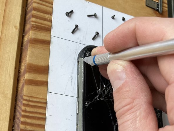
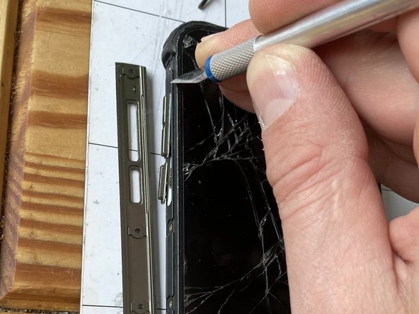
- Use a spudger or a utility knife to pry off the side bezels.
- Pry in one corner and separate the back.
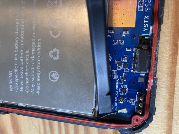
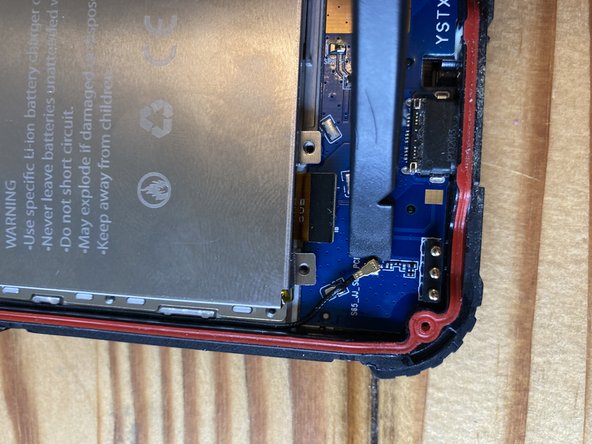
- Use a plastic spudger to disconnect the flex connectors.
- Use a plastic spudger to disconnect the flex connector and the antenna
- Heat up this PCB with either iOpener or a heat gun on low temp (100-120 Celsius) to loosen the adhesive and pry it off from the side.
- Remove the screws.
- The last screw is under a tamper-proof sticker
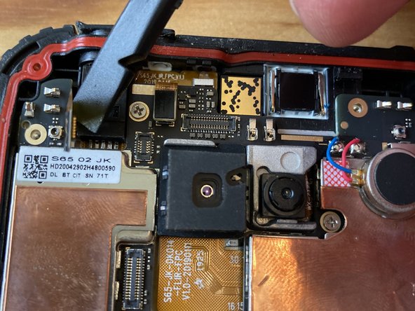
- Use plastic spudger or tweezers to disconnect the camera flex cable from the top
- Gently lift up the plasctic cover from the right side. It is still connected to the board below!
- Disconnect the flex cable
- Disconnect the antenna
- Remove the screws from the battery cover
- Carefully release the ribbon cable from the battery shield. It is stuck down at two points.
- Disconnect the flex connectors and remove the battery
- Remove two J000 screws
- Carefully pry up the camera. Heat from the glass side if necessary.
- Unscrew and remove the camera assembly
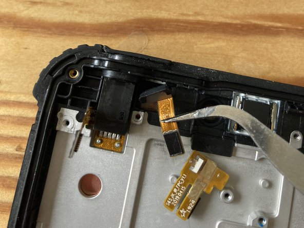
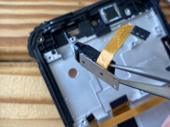
- Heat the light sensor from both sides to loosen the adhesive and gently pry them out of their sockets
- Using tweezers slowly and carefully lift out the light sensor
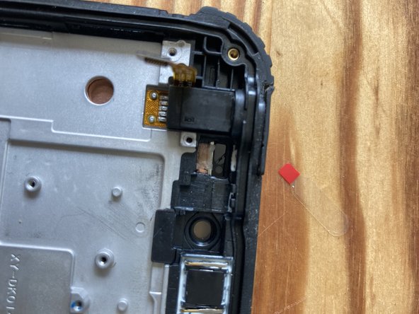
- Use some isopropyl alcohol if necessary to loosen the glue further on the audio jack
- Grab it with strong tweezers and wiggle from side to side and upwards until it comes out. Heat further if necessary.
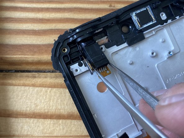
- Lift it out and transfer to the new screen.
- Gently peel the flex cable u p and transfer to the new assembly.
- Heat it up if the adhesive is too strong.
- Heat up and pry up the bottom PCB (charging port) and transfer to the new screen.