Diagnosis and Repair: Fencing Body Cord
ID: 149622
Description: A popular source of error in reporting...
Steps:
- First locate the fault location. To do this, connect one wire of the cable to a multimeter (continuity tester) as shown in the picture and bend the cable slightly near a plug.
- Start bending at the connectors, slowly working your way down the length of the cable. Repeat for each conductor. If a cable break is found, mark the damaged area and the affected wire.
- Unscrew the connector where the fault is.
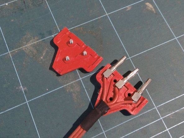
- If only one wire has slipped out of the bunched connector, continue with step 10. Otherwise mark wire no. 1 (see photo!) at least 1 cm behind the faulty spot (seen from the plug).
- Cut the cable 1 cm before the marking (seen from the plug) with side cutters.
- Remove the bunch plugs from the wires. It may be that the screws are secured with a small amount of varnish, which breaks when unscrewed.
- Now the cores of the rest of the body cable must be separated from each other. To do this, cut the cable between the wires over a length of 30-35 mm using the cutter knife on the cut-resistant surface.
- Warning: Make sure you really only cut between the individual wires and don't damage the wires!
- Caution: the cables usually have a tough silicone jacket, cutting them is a bit difficult!
- Alternatively - with stronger cables - only 5 mm can be cut at the end between two wires. The wires can then be pulled apart by hand.
- Strip the cores over a length of 8 mm. Then twist the bare strands a bit.
- Warning: stripping is difficult because of the silicone coating, with automatic pliers it may not be possible at all!
- Use crimping pliers to press the ferrules (1 mm²) onto the strands.
- Screw the bunched plugs back onto the wires. Tighten the screws. Caution: do not use too much force, otherwise the drive of the screws can break out!
- The screws can be secured against unscrewing under light loads with a small amount of low-strength locking varnish (e.g. LocTite 222).
- Insert the bunch plugs into one half of the cable plug. Make sure that the marked wire is in position 1 (see photo).
- The screws in the bunched plugs must point to the side, otherwise the plug cannot be screwed on properly.
- A bell connector can be used as an alignment aid (see photo).
- Screw the cable connector together.
- Tip: Only then pull off the bell connector.
- Reconnect the multimeter as shown in the photo. Again check all wires for continuity, bending them slightly.