Tivoli One Variable capacitor Repair
ID: 151226
Description: The Tivoli One is a nice little radio with...
Steps:
- Turn off the Tivoli One and disconnect the power cord.
- Unscrew the six #2 Phillips screws on the back panel.
- Carefully pull out the rear panel a few centimeters, but do not remove it. It is still connected by the cables.
- Mark the connectors on the tuner board with a colored felt-tip pen so that you can plug them back in correctly later. Then pull them off.
- In this picture the parts have already been removed.
- Pull out the front and the back completely.
- Remove the tuner.
- Unscrew the three Phillips screws #1 and carefully lift the tuner board upwards.
- Mark the position of the coupling with a felt pen to make it easier to insert it later.
- Detach the medium wave antenna -the black wire frame- from the back; it is no longer needed.
- The blue VHF antenna remains. However, it is recommended to operate the device with an external antenna - a simple wire of 80 cm length is often sufficient.
- This step is a bit tricky and tedious. Work very carefully and slowly. Mark the setting of the coupling with a felt pen.
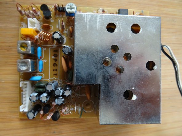
- Very carefully desolder the shields above the variable capacitor. Start with the flatter part on the back. There are ten solder joints on the front and back. Use a desoldering suction pump or desoldering braid. Remove the shields on the front and back.
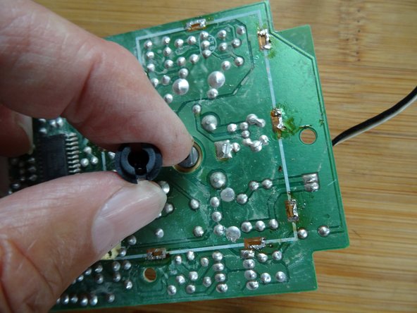
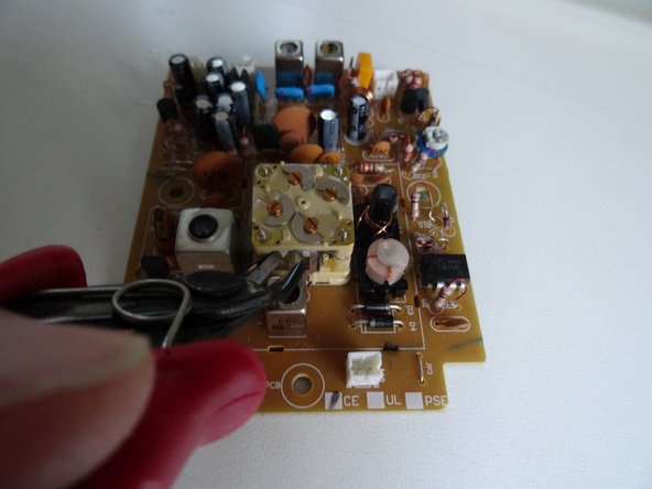
- Inside the black coupling piece, there is a Phillips screw. Unscrew it. Remove the circlip; it is loose.
- Carefully pull off the black coupling piece.
- Pull the cap off the variable capacitor.
- Cut through the two bars connecting the upper and lower parts of the capacitor using side cutters.
- Unscrew the four very small nuts that hold the capacitor together.
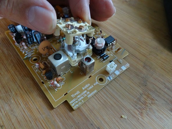
- Lift the upper part very carefully upwards.
- On the bottom of the top cover, directly on the shaft, is a small brass washer. Do not lose it!
- Attention: Left-hand thread! Unscrew the nut on the axle clockwise.
- Here you can see the cause of the malfunction: the white separating agent between the plates of the capacitor has dried out. It must be removed. The lower plates are for FM, the upper ones for medium wave. The upper ones will not be needed later.
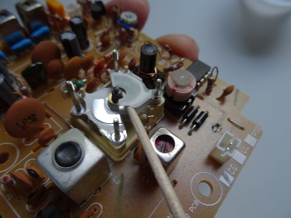
- Slowly and patiently remove all the innards of the variable capacitor. A toothpick is good for this.
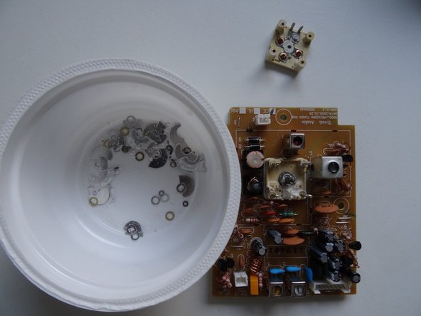
- On the shaft are rotating rotors, fixed stators and washers. Other very small washers are on the upright posts
- You don't need to sort the parts, we'll come to that later. But be careful not to lose or damage any of the very small parts.
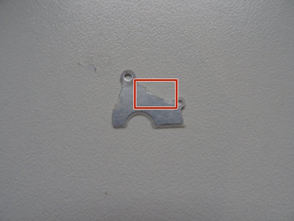
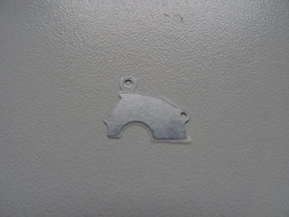
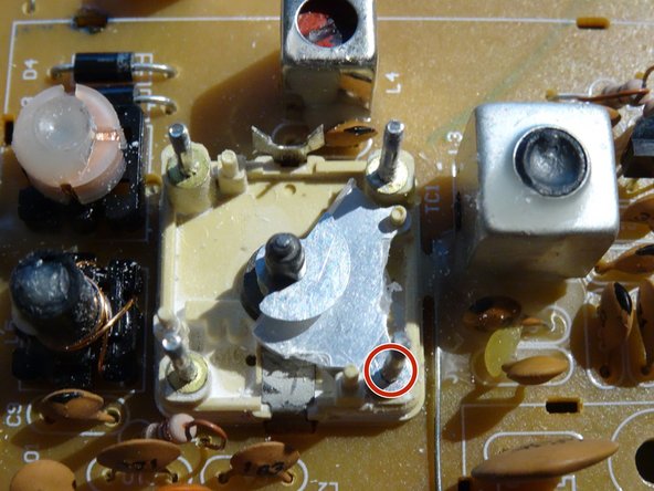
- There are four different types of stators. The two shown here are still needed. They can be recognized by the long indentation at the "back" (marked red):
- 2 pieces type 1
- 2 pieces type 2
- The two shown here are for AM and will be omitted in the future:
- 2 pieces type 3 with T-shaped eyelet on the right side
- 4 pieces type 4 with short indentation at the back
- Here are the various washers:
- 10 pieces of brass
- One thicker brass washer
- various silver ones
- some very small silver ones from the posts
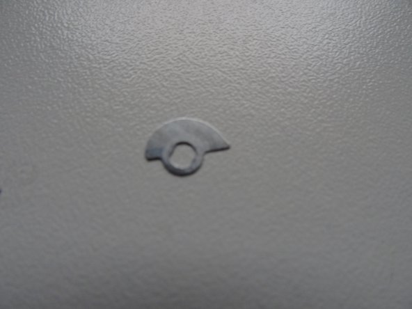
- the oval washer is not needed anymore
- And here are the rotors. Only the type of which there are six is needed; the others are omitted.
- Now comes the cleaning work:
- Push out the shaft. Clean the shaft and its contact ring (marked red) on the lower part of the condenser well with isopropyl alcohol, and scrape off any corrosion.
- Reinsert the shaft. The stop must be on the far right.
- Clean the four required stators (type 1 and type 2), the six rotors, and all disks well with isopropyl alcohol. Use a lint-free cotton swab for this purpose.
- The assembly follows. Work very carefully with a toothpick and tweezers; do not damage the parts!
- Place the capacitor as shown in picture 1. Start with a rotor.
- ... then a brass washer
- Next is a stator of type 2
- ...a rotor
- ...and a brass washer
- one of the tiny washers is put on the post.
- And again:
- Rotor
- Brass washer
- Stator type 2
- Rotor
- Silver disc
- Then turn the capacitor 180°.
- Next is the next rotor; this one and the two remaining are twisted 180° against the first three rotors.
- Then, a type 1 stator. The stators are also twisted by 180°, and then the brass disc.
- Tiny disc on the post.
- Rotor, brass disk.
- Type 1 stator
- Rotor
- And then the thick brass disc to finish.
- Press the shaft down again.
- The washers for the AM tuning are no longer installed and are replaced by three washers and two snap rings of size M3. Then tighten the axle nut again. Reminder: Left-hand thread, so counterclockwise. Do not tighten the nut too much; light tension is enough.
- Fill the remaining washers on the two marked items.
- Put the small washer that was between the top of the condenser and the axle (see step 5) back on the axle. Oil it very lightly.
- Carefully replace the top of the condenser. Check if the axle can be turned. Then screw the four small nuts back on, but not too tight. Always check if the axle with the rotors turns freely; maybe you have to put more spacers on the posts.
- Put a small solder dot on the wire between the upper and the lower part.
- Replace the protective cap.
- Now you have to test and adjust. Caution: the power cable is well insulated, but always remember to be careful!
- Reconnect all connections between the front and the rear panel correctly.
- Switch the unit to FM - you should hear at least a slight hiss. Remember the switch for the antenna on the back; an external one works better in case of doubt.
- Adjust the variable capacitor until - hopefully - the first station can be heard - and be happy! The most important part is done.
- Disconnect the connections again.
- Solder the two shields again; a few solder points are sufficient enough.
- Put the tuner board on and attach it with the three screws. Play a bit with the adjustment knob until the coupling fits.
- ...and connect the parts again, this time for the adjustment work.
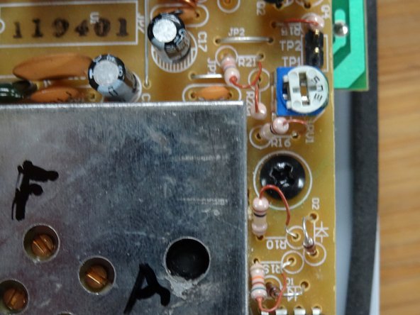
- The dial marked F controls the frequency. Set the dial to the frequency of a known station at about 100 MHz, use a second radio, and adjust until the desired station can be heard clearly on both radios.
- Set a weaker station at about 100 MHz and adjust with A to best volume.
- This potentiometer allows you to adjust the LED transmitter setting to the optimum level. Set a strong transmitter and adjust the yellow LED to the highest brightness.
- Disconnect the connections between the front part and the back part for the last time.
- First, push the front part completely into the housing, then the back part, but not completely.
- Re-establish the connections and tighten the unit with the six housing screws.