Flipper Zero Teardown
ID: 151455
Description: Flipper Zero is a portable multi-tool for...
Steps:
- Do not use alcohol or alcohol containing cleaners, tissues, wipes, or sanitizers on the acrylic window! It can permanently damage it.
- The top shell, the IR cover and the acrylic window are one solid part and can't be disassembled. (They pop out with a bit of force but wont go back in as well without some sort of glue)
- The Flipper Zero only uses two types of screws:
- Long screw size is M1.7x8
- Short screw size is M1.7x4
- Eject the microSD card (if present) by pressing it with your fingernail.
- Use a PH0 screwdriver to unscrew the four long screws holding the back cover.
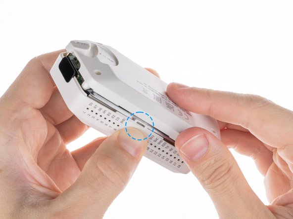
- Press the middle of the top cover on both sides, one by one, to release the latches that hold the back cover in place.
- Once the latches are released, you can remove the bottom cover.
- The board with the NFC antenna is glued to the bottom cover with adhesive tape.
- To remove the board, gently pry one of the edges of the board with a plastic pick to peel off the adhesive tape.
- Gently pull out the rest of the board.
- Use a PH0 screwdriver to unscrew the two short screws that are holding the chassis and top cover together.
- Take the chassis out of the case.
- Disconnect the battery by prying the connector with a plastic pry tool and pulling it out.
- Do not use a metal screwdriver when prying out battery connectors, if you do it may short the battery terminals and cause damage to the battery.
- Disconnect the large ribbon cable from the board. Use a plastic pick to lift the latch up to release the locks.
- Once the connectors are unlocked, carefully pull out the ribbon cables.
- Unscrew the short screw holding the iButton board in place using a PH0 screwdriver.
- Once the screw is removed, carefully remove the iButton board.
- To disconnect the flat cable from the iButton board, use a flat screwdriver to carefully release the lock by pulling the latch up, then pulling gently on the ribbon cable.
- Once the connector is unlocked, gently pull the cable out of the connector.
- To release the battery chassis, gently rock it back and forth while pulling the two parts apart.
- To remove the NFC RFID board, release it from the latches in the sequence shown.
- Release the board from the latches by pressing on the edge of the chassis near the specific latch in the specified sequence.
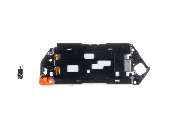
- Take out the vibration motor.
- To remove the lace mount, use a PH0 screwdriver to unscrew the short screw that is securing it in place.
- Remove the lace mount from the chassis.
- The battery is attached to the chassis with double-sided tape. To remove it, use a plastic pick to gently peel the battery off the chassis.
- Caution: Don't jab the battery with any sharp tools. A punctured battery may leak dangerous chemicals or catch fire.
- Remove the battery from the chassis.
- Use a plastic pick to lift the latch up to unlock the connector.
- Pull the flat cable out.
- Unscrew the two short screws holding the button chassis using a PH0 screwdriver.
- To disconnect the button chassis and the board, press the latch on the side shown below.
- Remove the button chassis.
- Disconnect the screen ribbon cable from the board. Use a plastic pick to lift the latch up to open the lock.
- Remove the cable from the board.
- To remove the screen you need to desolder two contacts.
- Be careful during this step not to accidentally melt or desolder other nearby components.
- To remove the buttons you need to release the latches.
- OK
- D-pad
- Back
- The central button (OK) is removed after the navigation button (D-pad)
- Release the latches with a flat screwdriver. You need to be careful with the springs under the buttons.
- Use a flat screwdriver to release the light guide from the chassis.
- Pull the light guide out from the inside of the chassis.
- Here you can see all the parts laid out together.