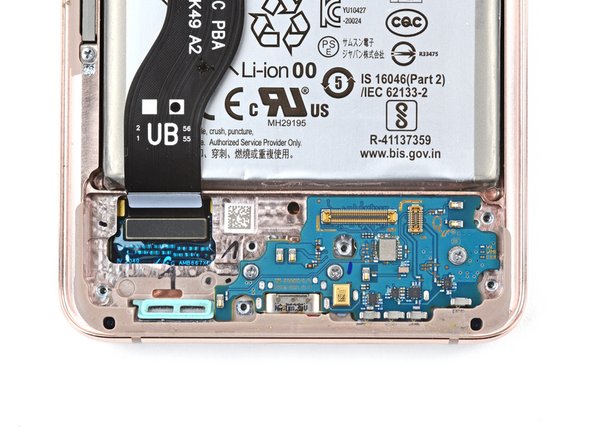
Samsung Galaxy S21+ USB-C Charging Port and Daughterboard Replacement
ID: 151732
Description: Use this guide to replace the USB-C charging...
Steps:
- Insert a SIM eject tool, bit, or straightened paper clip into the SIM card tray hole on the top edge of the phone.
- Press the SIM eject tool into the SIM card tray hole to eject the SIM card tray.
- Remove the SIM card tray.
- If you accidentally inserted the SIM eject tool into a microphone hole, don't worry! You most likely didn't damage the microphone.
- Be sure to power off your device before you begin your repair.
- Heat an iOpener and apply it to the bottom edge of the back cover for two minutes.
- A hair dryer, heat gun, or hot plate may also be used, but be careful not to overheat the phone—the display and internal battery are both susceptible to heat damage.
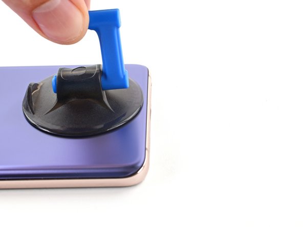
- Secure a suction handle to the bottom edge of the back cover, as close to the edge as possible.
- If the back cover is cracked, the suction handle may not stick. Try lifting it with strong tape, or superglue the suction handle in place and allow it to cure so you can proceed.
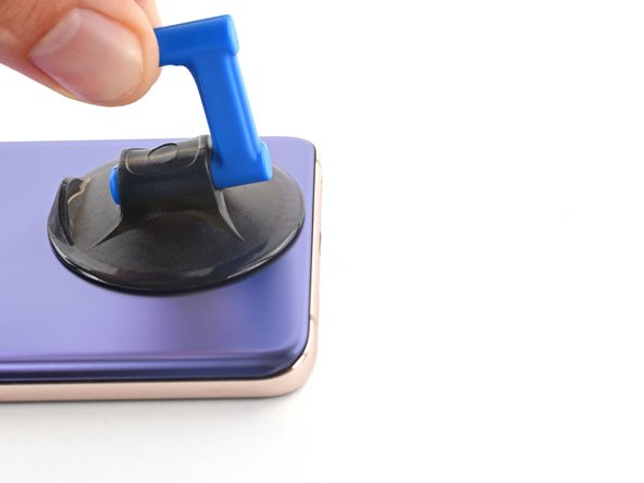
- Lift the back cover with the suction handle to create a small gap between the back cover and the frame.
- If you have trouble creating a gap, apply more heat to further soften the adhesive. Follow the iOpener instructions to avoid overheating.
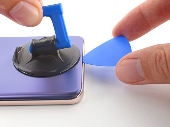
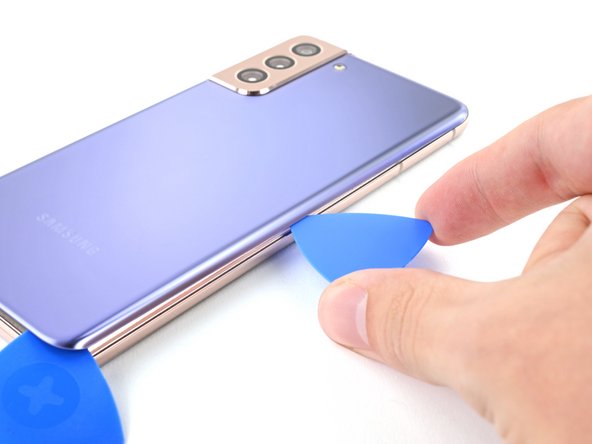
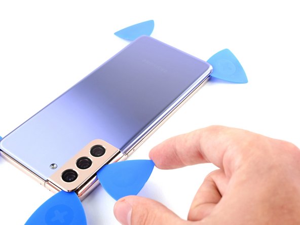
- Insert an opening pick into the gap you created.
- Slide the opening pick to the bottom left corner to slice the adhesive.
- Leave the opening pick in place to prevent the adhesive from resealing.
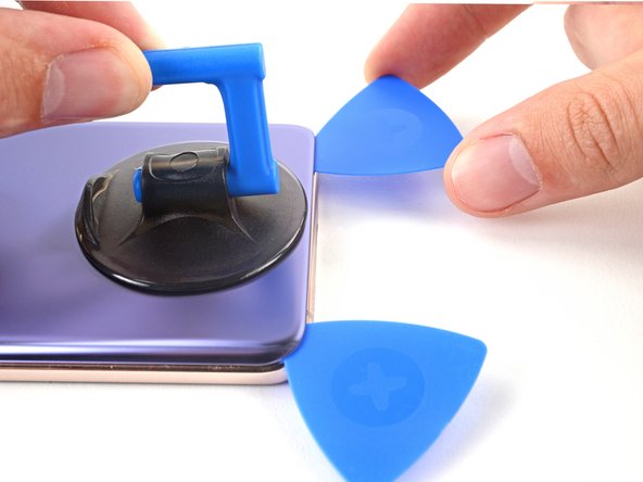
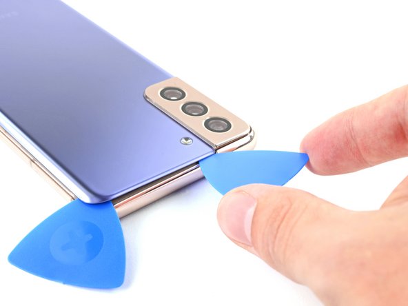
- Insert a second opening pick at the bottom edge of your phone.
- Slide the opening pick to the bottom right corner to slice the adhesive.
- Leave the opening picks in place to prevent the adhesive from resealing.
- Heat an iOpener and apply it to the right edge of the back cover for two minutes.
- If the adhesive becomes hard to cut, it has most likely cooled down. Apply a heated iOpener to the edge to reheat it.
- Insert a third opening pick at the bottom right corner of your phone.
- Slide the opening pick along the right edge of your phone to slice the adhesive.
- Leave the opening pick in the top right corner to prevent the adhesive from resealing.
- Heat an iOpener and apply it to the top edge of the back cover for two minutes.
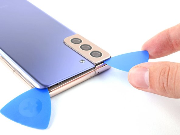
- When you slice near the camera assembly, insert only the tip of the opening pick (~4-5 mm) to avoid damaging or smearing the camera.
- Insert a fourth opening pick underneath the top right corner of your phone.
- Slide the opening pick along the top edge to slice the adhesive.
- Leave the opening pick in the top left corner to prevent the adhesive from resealing.
- Heat an iOpener and apply it to the left edge of the back cover for two minutes.
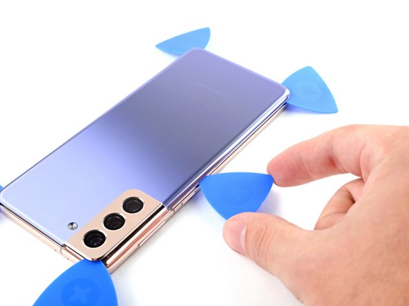
- Insert a fifth opening pick underneath the bottom left corner.
- Slide the opening pick along the left edge of the back cover to slice the remaining adhesive.
- When you slice near the power button, insert only the tip of the opening pick (~3-4 mm) to avoid damaging the power and volume button flex cable.
- Remove the back cover.
- During reassembly:
- This is a good point to power on your phone and test all functions before sealing it up. Be sure to power your phone back down completely before you continue working.
- Remove any adhesive chunks with a pair of tweezers or your fingers. Use some high concentration (over 90%) isopropyl alcohol to wipe away any adhesive residue.
- If you're using custom-cut adhesives, follow this guide.
- If you're using double-sided tape, follow this guide.
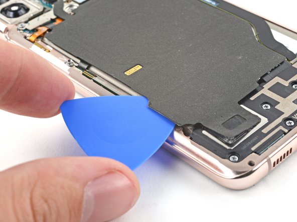
- Take care not to puncture or bend the battery with your tool—a punctured or bent battery may leak dangerous chemicals or cause a thermal event.
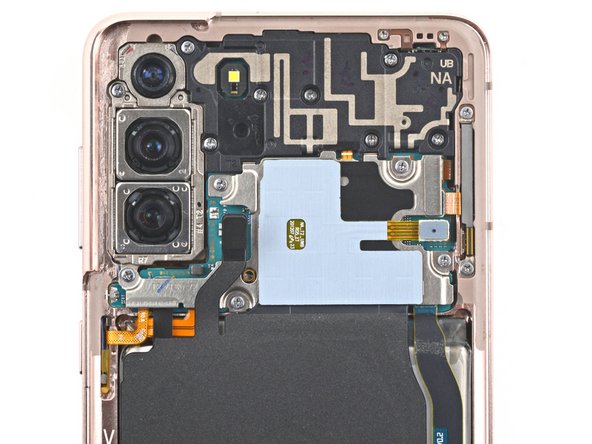
- Insert an opening pick underneath the left bottom end of the NFC antenna and charging coil assembly.
- Carefully slide the opening pick along the bottom left edge of the assembly to separate it from the battery.
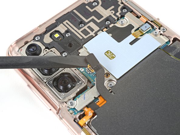
- Use a spudger to disconnect the charging coil by prying the connector straight up from its socket.
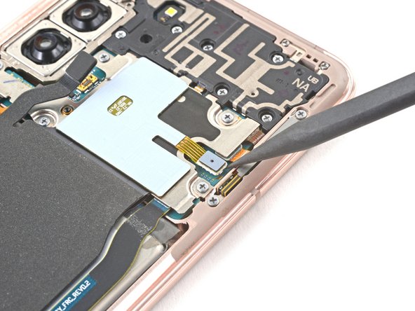
- Use a spudger to disconnect the NFC antenna by prying the connector straight up from its socket.
- Use a Phillips screwdriver to remove the five 3.9 mm-long screws securing the NFC antenna and charging coil assembly.
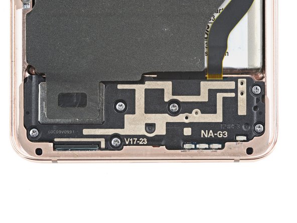
- Use a Phillips screwdriver to remove the six 3.9 mm-long screws securing the loudspeaker assembly.
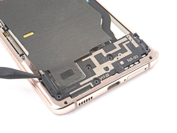
- Insert the tip of a spudger between the frame and the upper-left notch in the loudspeaker.
- Pry up with the spudger to release the loudspeaker from its plastic clips.
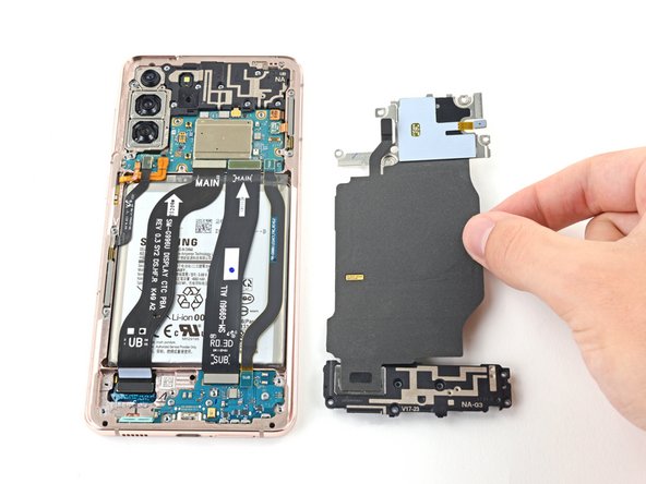
- Use a pair of tweezers or your fingers to carefully remove the NFC antenna and charging coil assembly.
- Use a spudger to pry up and disconnect the battery's press connector.
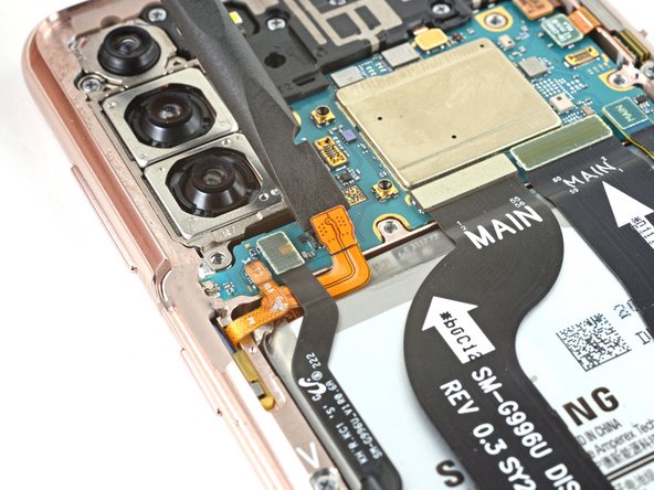
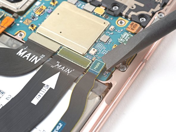
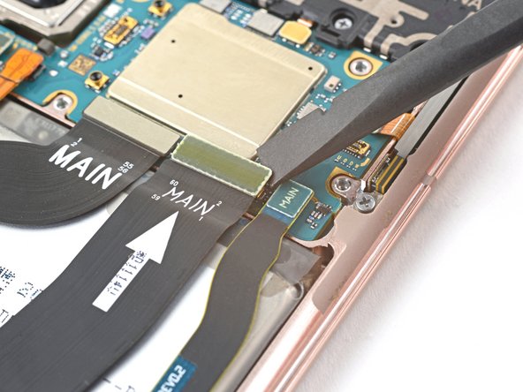
- Use a spudger to pry up and disconnect the primary and secondary interconnect cables' press connectors on the motherboard.
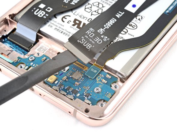
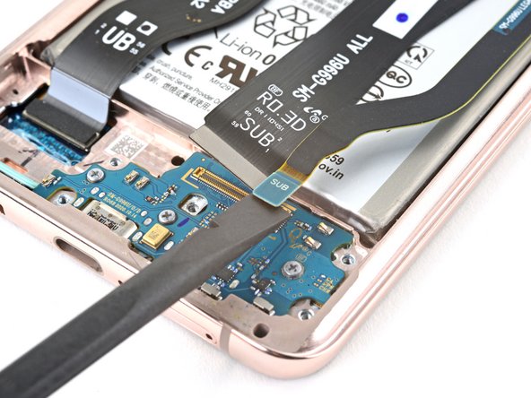
- Use a spudger to pry up and disconnect the primary and secondary interconnect cables' press connectors on the daughterboard.
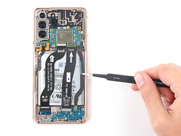
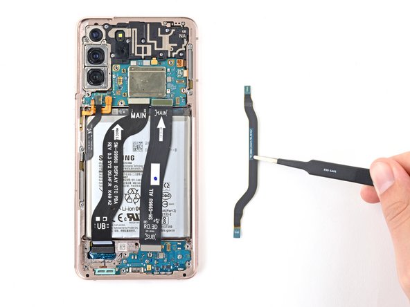
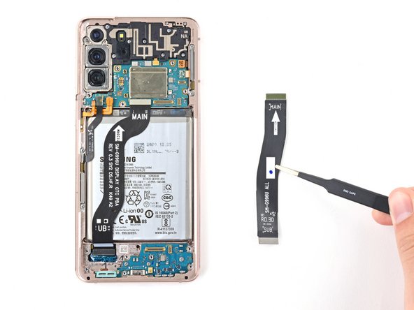
- Use tweezers, or your fingers, to remove the interconnect cables.
- Set the cables aside. You'll reuse them during reassembly.
- Use a Phillips screwdriver to remove the three 3.4 mm-long screws securing the charging board.
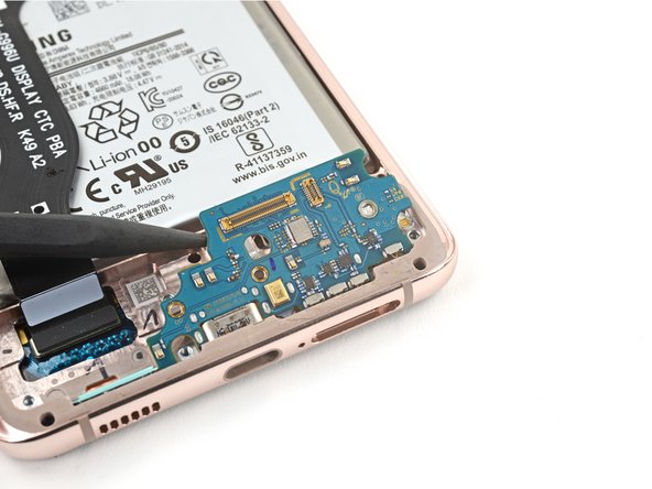
- Insert the pointed end of a spudger under the upper left edge of the daughterboard and pry up to release it from its recess.
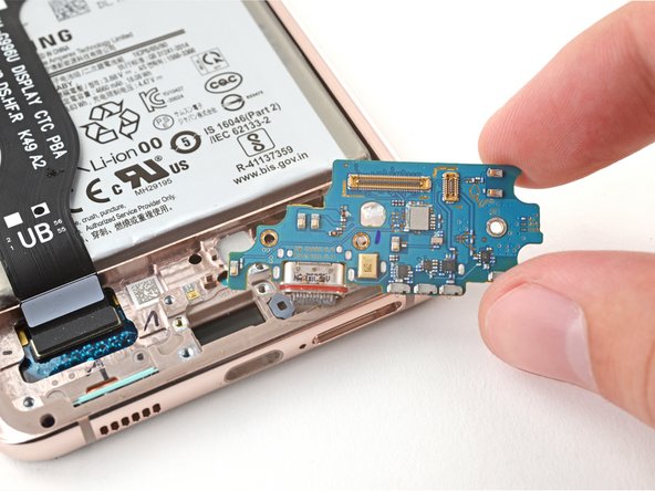
- Use tweezers, or your fingers, to pull the daughterboard up and away from the bottom of the device and remove it.