Samsung Galaxy Tab S7+ 5G Battery and Frame Assembly Replacement
ID: 151849
Description: Follow this guide to replace the battery and...
Steps:
- Completely power off your device before you begin.
- Apply a heated iOpener to the bottom edge of the device for three minutes to loosen the adhesive underneath.
- The display adhesive of the Galaxy Tab S7+ is extremely strong, and it's likely you need to reheat and reapply the iOpener several times before starting the display removal and during the removal procedure.
- A hair dryer, heat gun, or hot plate may also be used, but be careful not to overheat the device.
- While you're waiting for the adhesive to loosen, note the following:
- There's a long circuit board attached to the screen that sits parallel to the bottom edge.
- Don't insert the pick more than 2 mm to avoid damaging the circuit board.
- This image shows an example of a damaged display separating from the glass panel.
- Don't insert the pick more than 3 mm to avoid damaging the display.
- Once the screen is warm to touch, apply a suction handle to the bottom edge of the screen and as close to the edge as possible.
- If your screen is badly cracked, covering it with a layer of clear packing tape may allow the suction cup to adhere. Alternatively, very strong tape may be used instead of the suction handle. If all else fails, you can superglue the suction cup to the screen.
- Lift the screen with the suction handle to create a small gap between the screen and the frame.
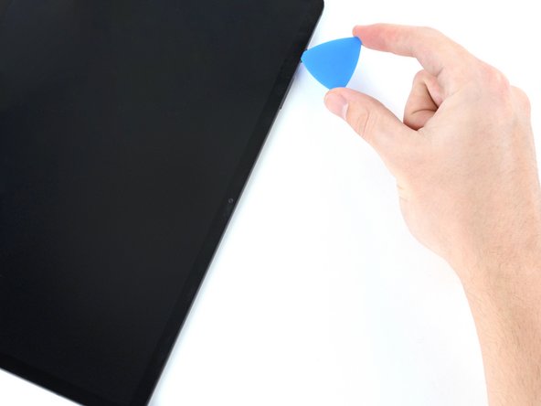
- Insert an opening pick into the gap between the frame and the screen.
- Don't insert the pick more than 2 mm to avoid damaging the circuit board.
- Leave the opening pick in place to prevent the adhesive from resealing.
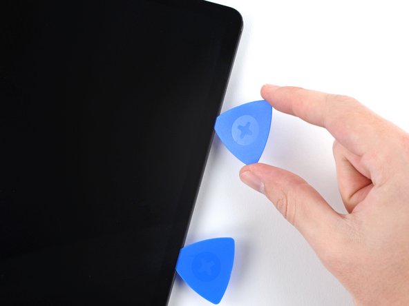
- Insert a new opening pick into the gap you created.
- Slide the new pick along the bottom edge of the device towards the bottom-right corner.
- Apply a heated iOpener to the right edge of the device for two minutes to loosen the adhesive underneath.
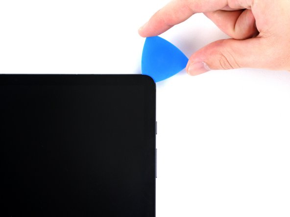
- Rotate the opening pick around the bottom-right corner of the device.
- Leave the opening pick in place to prevent the adhesive from resealing.
- Insert a new opening pick into the gap you created at the bottom right corner.
- Don't insert the pick more than 3 mm to avoid damaging the components along the right edge.
- Slide the new pick along the right edge of the device towards the top-right corner.
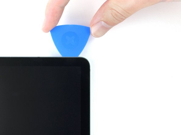
- Apply a heated iOpener to the top edge of the device for two minutes to loosen the adhesive underneath.
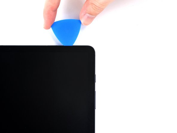
- Rotate the opening pick around the top-right corner of the device.
- Leave the opening pick in place to prevent the adhesive from resealing.
- Insert a new opening pick into the gap you created.
- Slide the new pick along the top edge of the device towards the top-left corner.
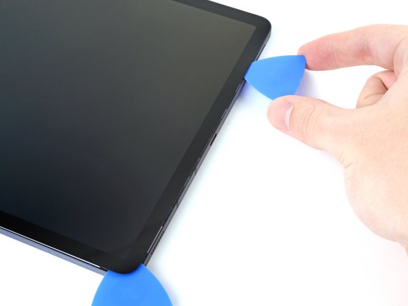
- Apply a heated iOpener to the left edge of the device to loosen the adhesive underneath.
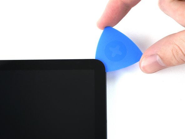
- Rotate the opening pick around the top-left corner of the device.
- Leave the opening pick in place to prevent the adhesive from resealing.
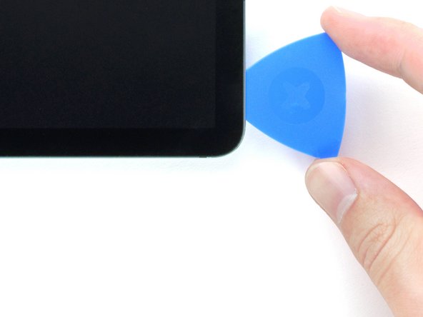
- Insert a new opening pick into the gap you created.
- Slide the new pick along the left edge of the device towards the bottom-left corner.
- Rotate the opening pick around the bottom-left corner of the device.
- Leave the opening pick in place to prevent the adhesive from resealing.
- At this point, the perimeter of the screen should be separated from the frame. If there's still resistance around the edges of the screen, use an opening pick to cut the adhesive again.
- Don't try to remove the screen all the way yet; it's still connected by a flex cable.
- With the top of the device facing you, lift the bottom edge of the screen up and away from you like you're opening a book.
- Rest the screen upside down before continuing.
- Be careful not to strain the flex cable.
- During reassembly:
- This is a good point to power on your tablet and test all functions before sealing it up. Be sure to power your tablet back down completely before you continue working.
- Remove any adhesive chunks with a pair of tweezers or your fingers. Use some high concentration (over 90%) isopropyl alcohol to wipe away any adhesive residue.
- If you're using custom-cut adhesives, follow this guide. If you're using double-sided tape, follow this guide.
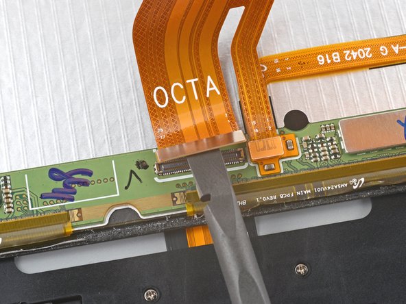
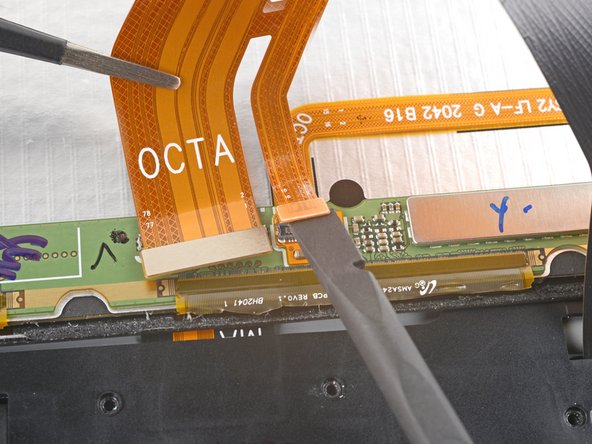
- Use the flat end of a spudger to pry up and disconnect the display cable's press connector from the back of the screen.
- Be careful not to damage the wide display flex ribbons on the bottom edge of the screen.
- To re-attach press connectors like this one, carefully align and press down on one side until it clicks into place, then repeat on the other side. Do not press down on the middle. If the connector is misaligned, the pins can bend, causing permanent damage.
- Use tweezers, or your fingers, to hold the display cable in place.
- Use the flat end of a spudger to pry up and disconnect the fingerprint sensor's press connector attached to the display cable.
- Take note of the display cable's position—you'll need to bend it in the same way when connecting a new screen.
- Remove the screen from the frame.
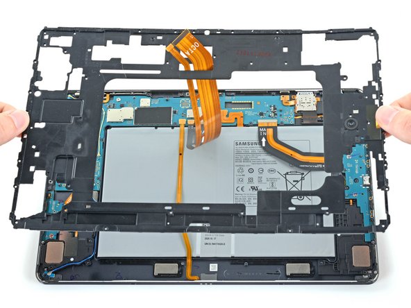
- Use a Phillips #00 screwdriver to remove the fifty 3 mm-long screws securing the frame bracket to the frame.
- The third photo has the same screws marked by quadrant. Use this photo during reassembly to help account for all the screws:
- Bottom left = 9 screws
- Bottom right = 14 screws
- Top right = 12 screws
- Top left = 15 screws
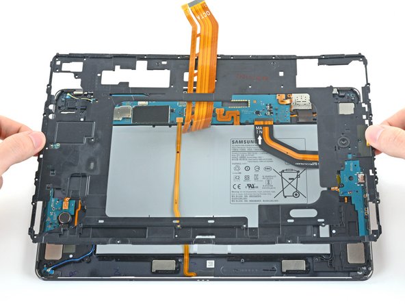
- Lift the frame bracket away from the frame, making sure to thread the display cable through its slot.
- Use the flat end of a spudger to pry up and disconnect the battery's press connector from the motherboard.
- Use the flat end of a spudger to pry up and disconnect the daughterboard interconnect cable's press connector from the motherboard.
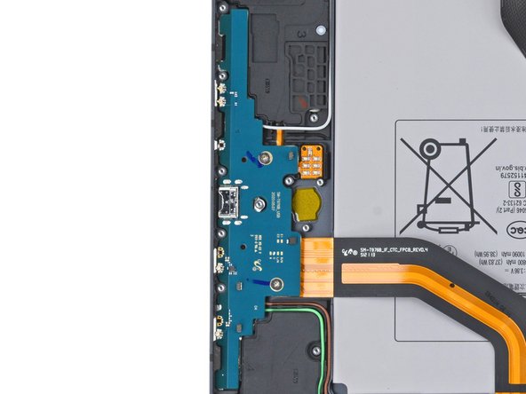
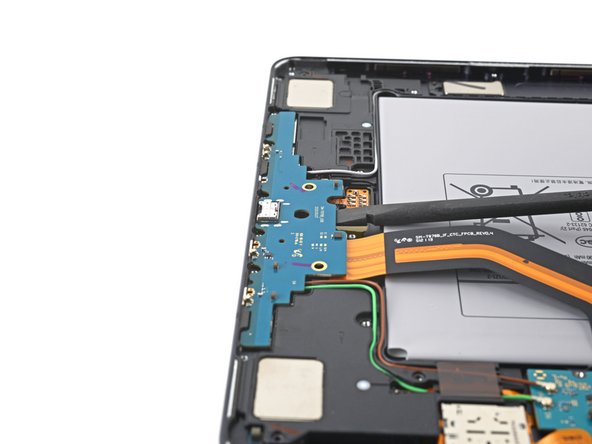
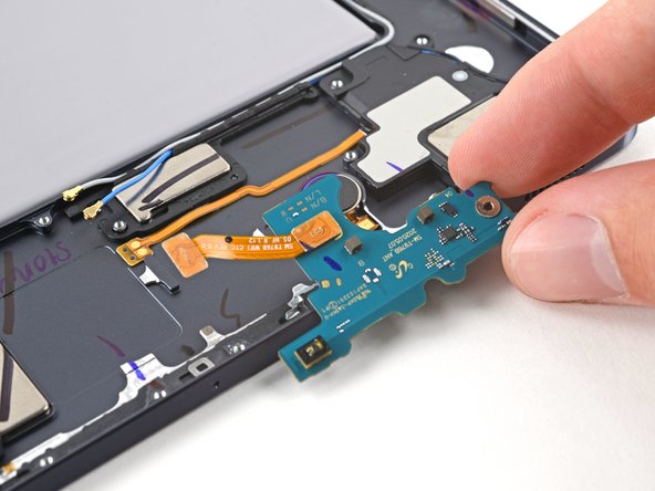
- Use a Phillips #00 screwdriver to remove the two 2 mm screws securing the charging daughterboard to the frame.
- Insert a spudger between the charging daughterboard and the frame.
- Pry up with the spudger to release the clips securing the charging daughterboard.
- Use your fingers to pull the charging daughterboard from its slot in the frame.
- Turn the charging board upside down, making sure not to twist the coaxial cables too far.
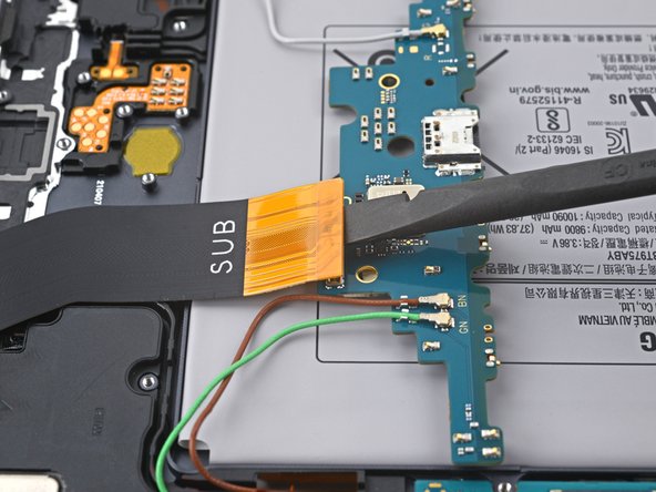
- Use the flat end of a spudger to pry up and disconnect the interconnect cable's press connector secured to the charging daughterboard.
- Use tweezers, or your fingers, to remove the interconnect cable.
- Set the cable aside. You'll reuse it during reassembly.
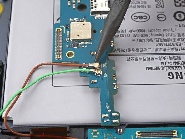
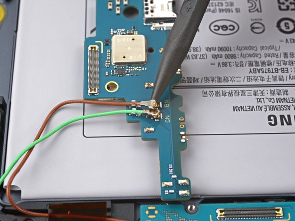
- Use the point of a spudger to carefully pry up and disconnect the brown and green coaxial cable from the bottom of the daughterboard.
- During reassembly, these can be tricky to reconnect. One at a time, hold each connector in place over its socket and press down with the flat end of a spudger. The connector should snap into place.
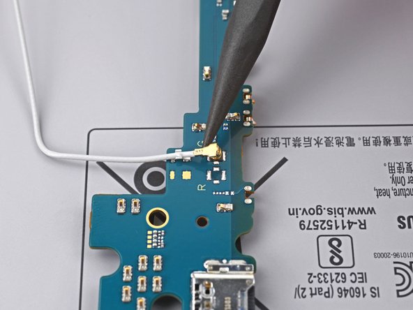
- Use the point of a spudger to carefully pry up and disconnect the white coaxial cable from the top of the daughterboard.
- Remove the daughterboard from the frame.
- During reassembly, reconnect the interconnect cable to the daughterboard before fastening the screws.
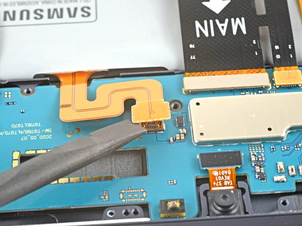
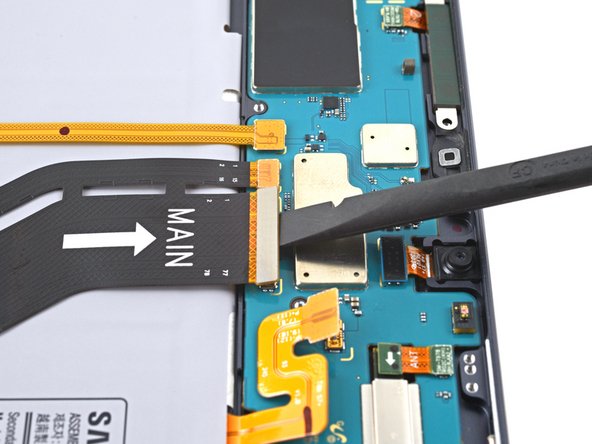
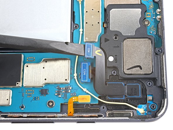
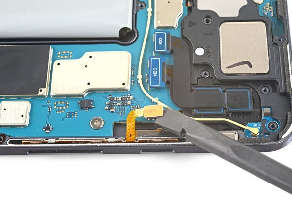
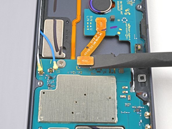
- Use the flat end of a spudger to pry up and disconnect the display cable's press connector secured to the motherboard.
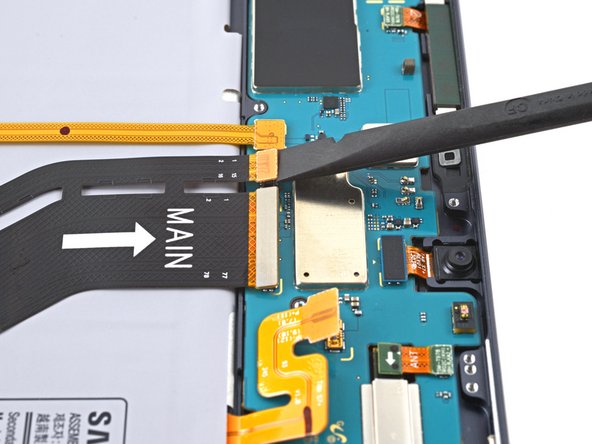
- Repeat for the fingerprint sensor cable attached to display cable.
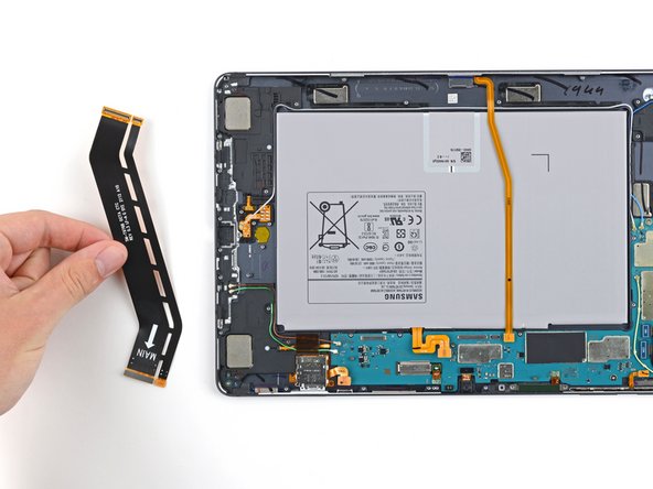
- Use your fingers to remove the display cable.
- Set the cable aside. You'll reuse it during reassembly.
- Use the flat end of a spudger to pry up and disconnect the keyboard dock port cable's press connector secured to the motherboard.
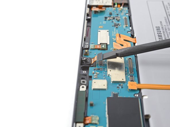
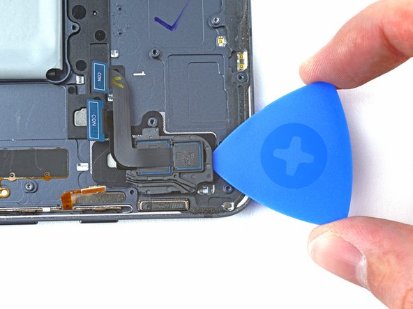
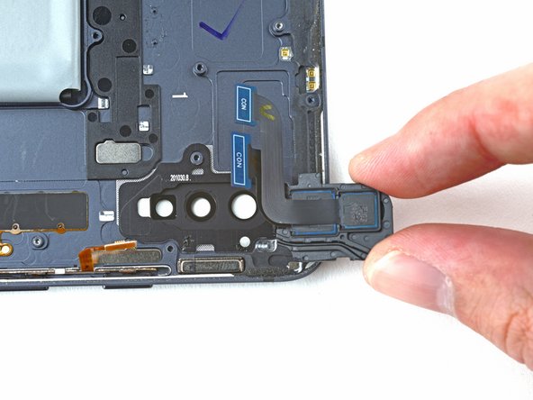
- Use the flat end of a spudger to pry up and disconnect the front camera's press connector secured to the motherboard.
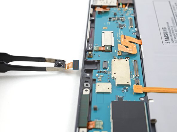
- Use tweezers, or your fingers, to remove the front camera.
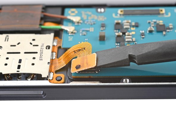
- Use the flat end of a spudger to pry up and disconnect the microSD card reader's press connector secured to the motherboard.
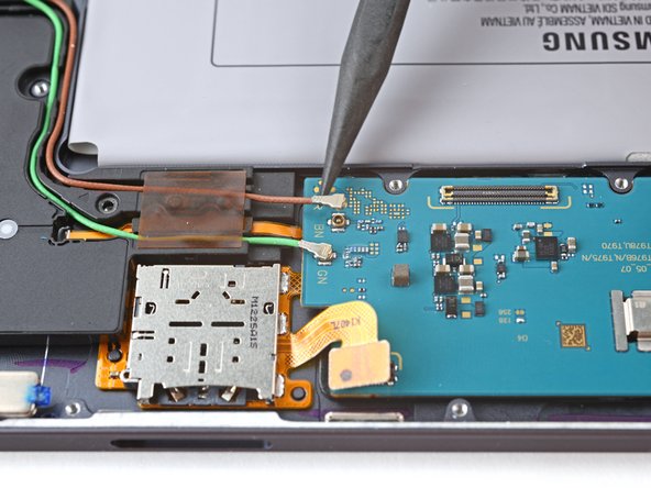
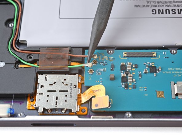
- Use the point of a spudger to carefully pry up and disconnect the green coaxial cable from the left side of the motherboard.
- Repeat this process for the brown coaxial cable.
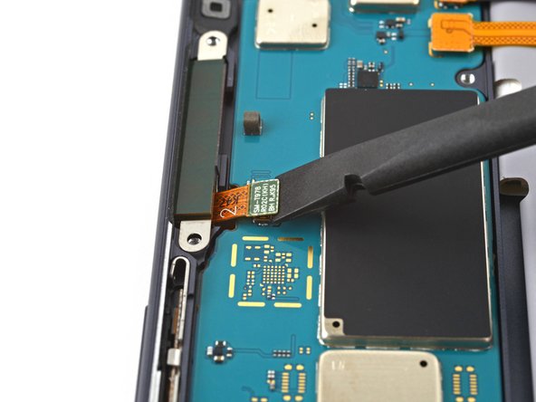
- Use the flat end of a spudger to pry up and disconnect the 5G mmWave antenna's press connector secured to the motherboard.
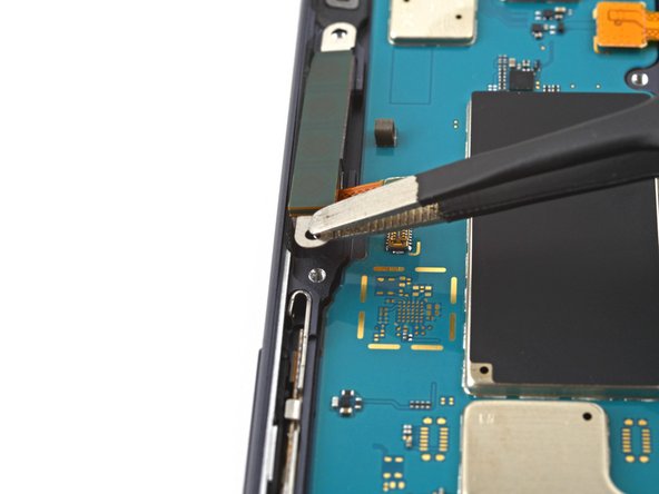
- Use tweezers to pull the antenna out of the frame by its bracket.
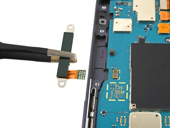
- Remove the 5G mmWave antenna.
- Set the antenna aside. You'll reuse it during reassembly.
- Use the flat end of a spudger to pry up and disconnect the rear camera's two press connectors secured to the motherboard.
- Use the flat end of a spudger to pry up and disconnect the power button cable's press connector secured to the motherboard.
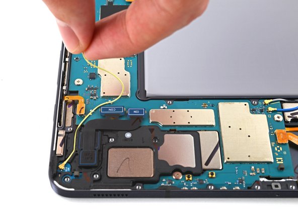
- Use the point of a spudger to carefully pry up and disconnect the bottom-right loudspeaker's yellow coaxial cable from the motherboard.
- Take care not to puncture the battery with your tool—a punctured battery may leak dangerous chemicals or cause a fire.
- During reassembly, these can be tricky to reconnect. One at a time, hold each connector in place over its socket and press down with the flat end of a spudger. The connector should snap into place.
- Pull the coaxial cable away from the frame, making sure the cable is completely unthreaded from the motherboard.
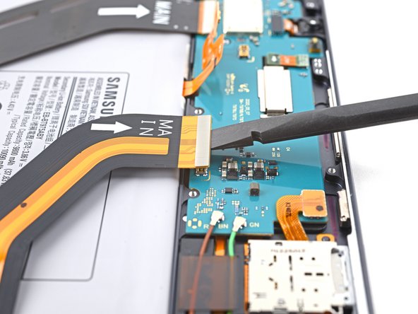
- Use the flat end of a spudger to pry up and disconnect the interconnect cable's press connector secured to the motherboard.
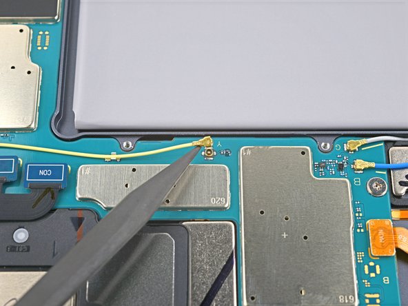
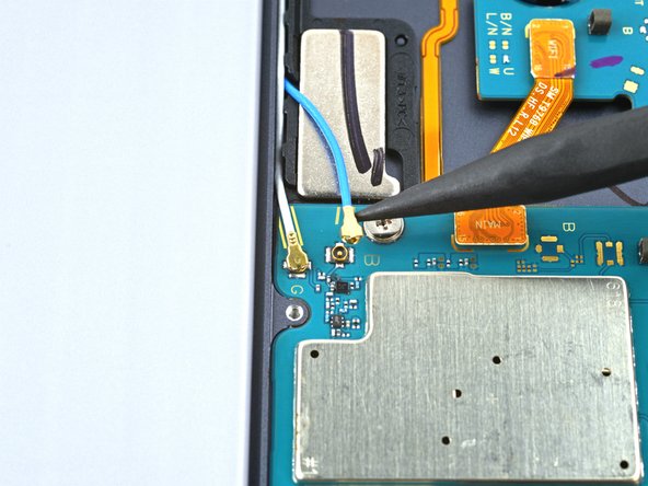
- Use the point of a spudger to carefully pry up and disconnect the top-right loudspeaker's blue coaxial cable from the motherboard.
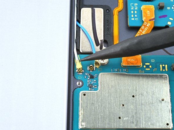
- Repeat this process for the white coaxial cable.
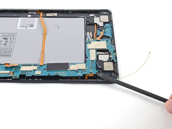
- Use a Phillips #00 screwdriver to remove the three 2 mm screws securing the motherboard to the frame.
- Insert a spudger into a gap between the motherboard and the frame.
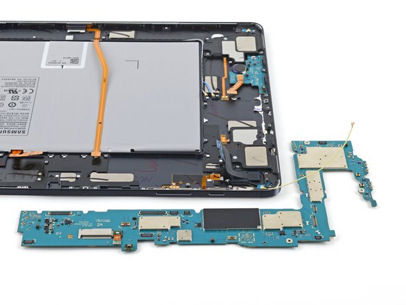
- Pry up with the spudger to release the motherboard from its clips.
- Remove the motherboard.
- During reassembly, refasten the motherboard screws first to properly align it into place, then reconnect the cables.
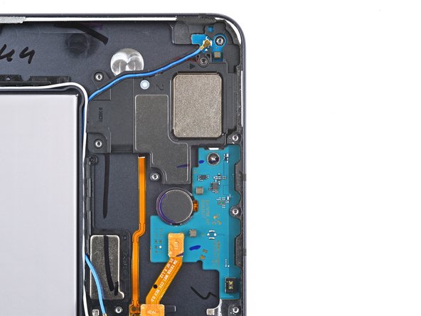
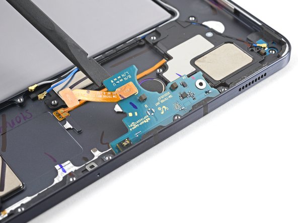
- Use a Phillips #00 screwdriver to remove the 2 mm-long screw securing the antenna board to the frame.
- Insert a spudger into a gap between the antenna board and the frame.
- Pry up with the spudger to separate the antenna board from the frame.
- Remove the antenna board.
- The keyboard dock port cable is lightly adhered to the frame.
- Apply a heated iOpener to the top of the device for 90 seconds.
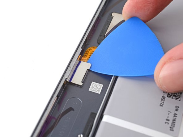
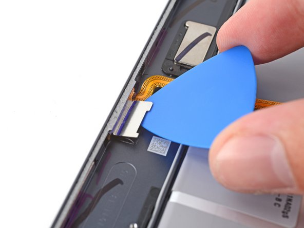
- Insert the tip of an opening pick between the frame and the keyboard dock port cable's metal bracket.
- Rotate the pick while prying up to separate the adhesive.
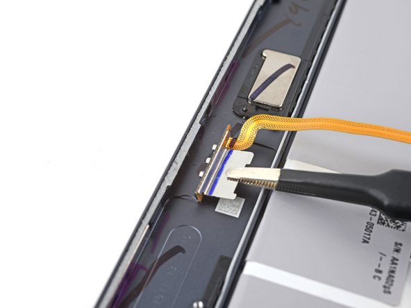
- Use tweezers, or your fingers, to pull the keyboard dock port cable directly out of its slot.
- Remove the keyboard dock port cable.
- Set the cable aside. You'll reuse it during reassembly.
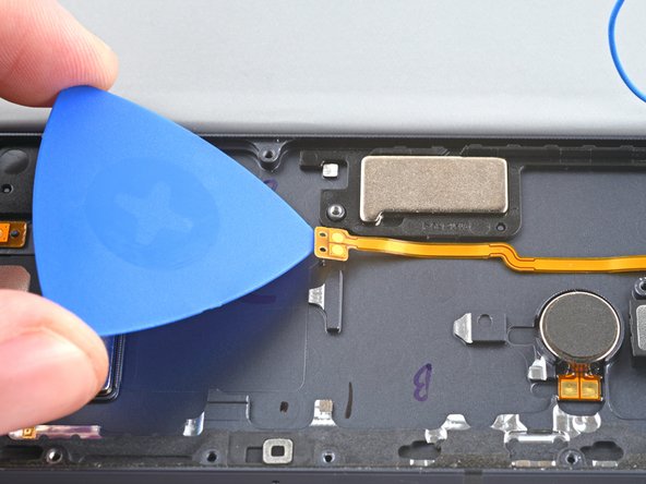
- The bottom-left loudspeaker's flex cable is secured to the frame by adhesive. Use heat to avoid tearing the connector.
- Apply a heated iOpener to the left edge of the device for two minutes.
- A hair dryer, heat gun, or hot plate may also be used, but be careful not to overheat the device.
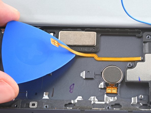
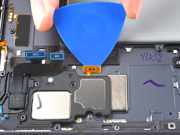
- Insert an opening pick between the bottom-left loudspeaker's copper connector pads and the frame.
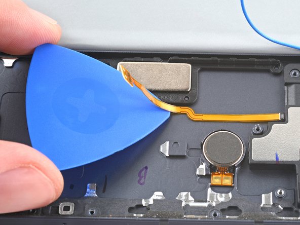
- Pry up while slicing the adhesive to separate the pad from the frame.
- Slice with the opening pick along the bottom of the connector's cable to completely separate it from the frame.
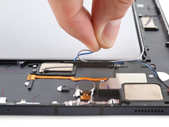
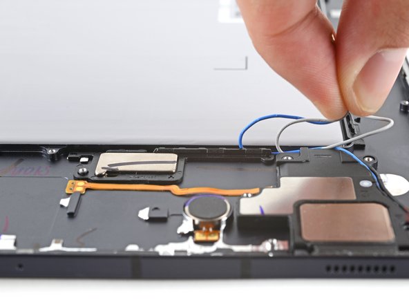
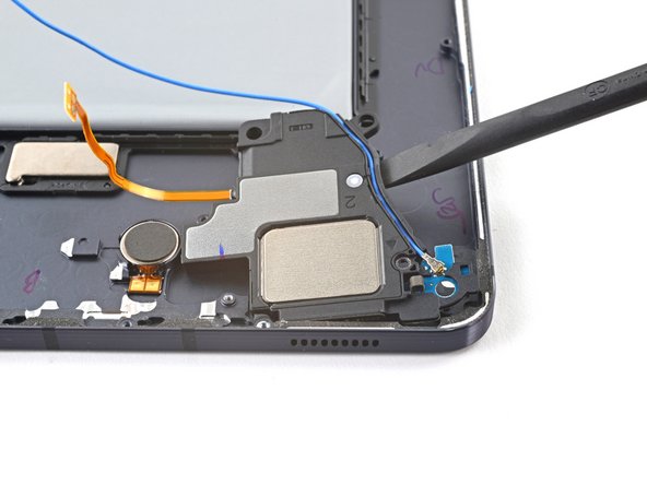
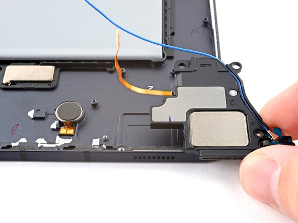
- Use your fingers to unroute the blue and white coaxial cables from their groove in the frame.
- Use a spudger to pry up and separate the loudspeaker from the frame.
- Remove the loudspeaker.
- Set the speaker aside. You'll reuse it during reassembly.
- During reassembly, rethread the blue coaxial cable after slotting the bottom-left speaker into your new frame.
- Insert an opening pick between the top-left loudspeaker cable and the frame.
- Slice the adhesive while prying up with the pick to separate the cable from the frame.
- Use a spudger to pry up and separate the top-left loudspeaker from the frame.
- Remove the top-left loudspeaker.
- Set the speaker aside. You'll reuse it during reassembly.
- The rear camera is secured to the frame by adhesive. Use heat to avoid damaging the camera.
- Apply a heated iOpener to the top-left corner of the device for two minutes.
- A hair dryer, heat gun, or hot plate may also be used, but be careful not to overheat the device.
- Insert an opening pick into a gap between the rear camera and the frame.
- Rotate the pick around edges of the rear camera to slice the adhesive.
- Pry up with the pick to separate the rear camera from the frame.
- Remove the rear camera.
- Set the camera aside. You'll reuse it during reassembly.
- The top-right loudspeaker's connector is secured to the frame by adhesive. Use heat to avoid tearing the connector.
- Apply a heated iOpener to the right edge of the device for two minutes.
- A hair dryer, heat gun, or hot plate may also be used, but be careful not to overheat the device.
- Insert an opening pick between the loudspeaker's connector pads and the frame.
- Slice the adhesive while prying up with the pick to separate the pads from the frame.
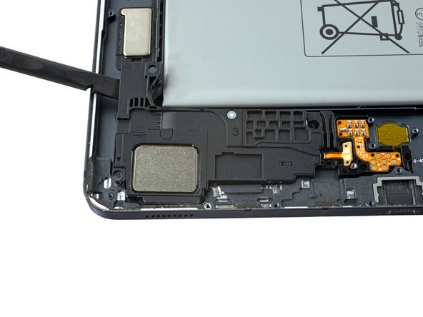
- Use a spudger to pry up and separate the loudspeaker from the frame.
- Remove the loudspeaker.
- Set the speaker aside. You'll reuse it during reassembly.
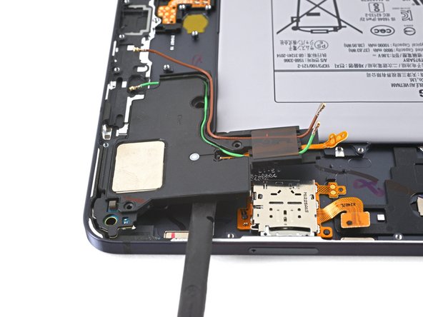
- During reassembly, rethread the green and brown coaxial cables after slotting the top-right speaker into your new frame.
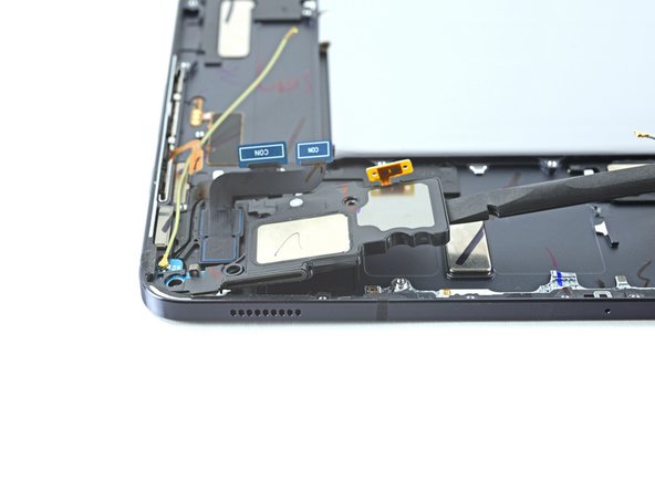
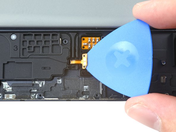
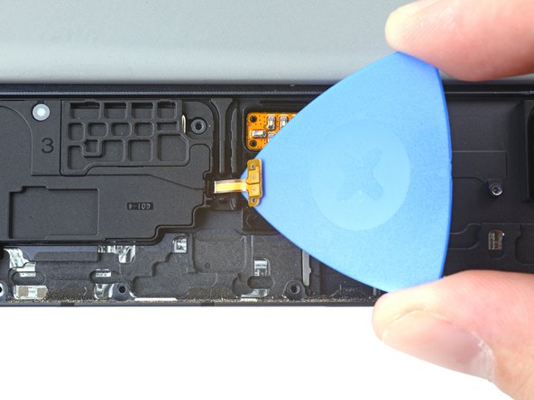
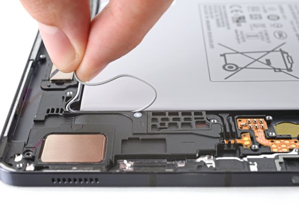
- Insert an opening pick between the bottom-right loudspeaker cable and the frame.
- Slice the adhesive while prying up with the pick to separate the cable from the frame.
- Use your fingers to unroute the white coaxial cable from its groove in the frame.
- You will need to transfer and rethread the white coaxial cable into your new frame.
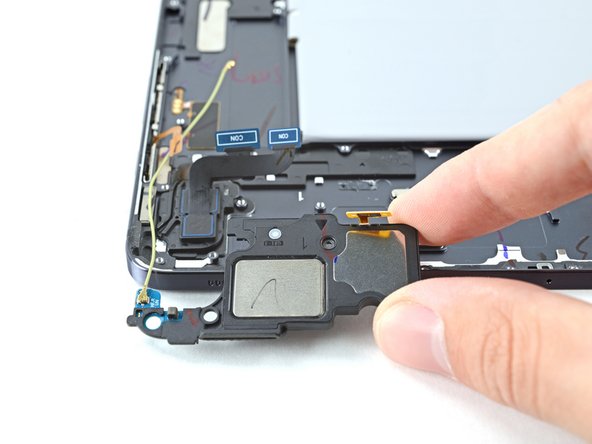
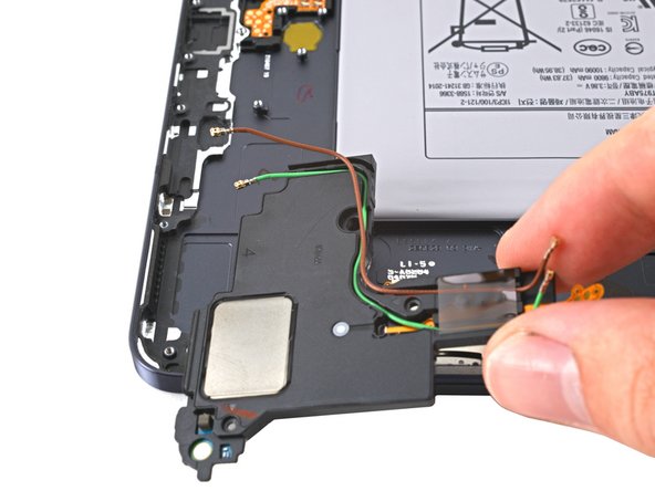
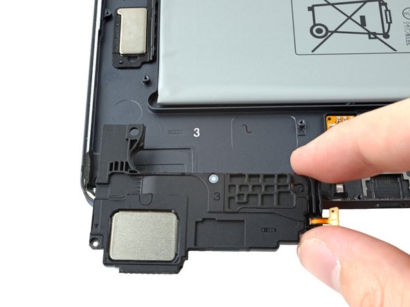
- Use a spudger to pry up and separate the bottom-right loudspeaker from the frame.
- Remove the bottom-right loudspeaker.
- Set the speaker aside. You'll reuse it during reassembly.
- During reassembly, rethread the white coaxial cable after slotting the bottom-right speaker into your new frame.
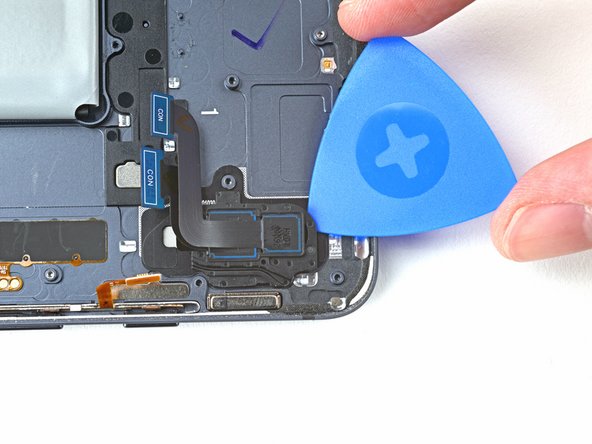
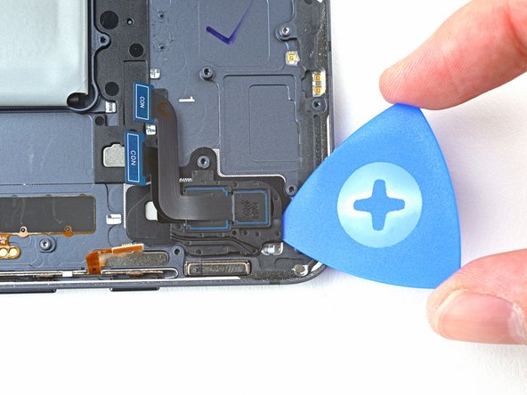
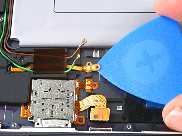
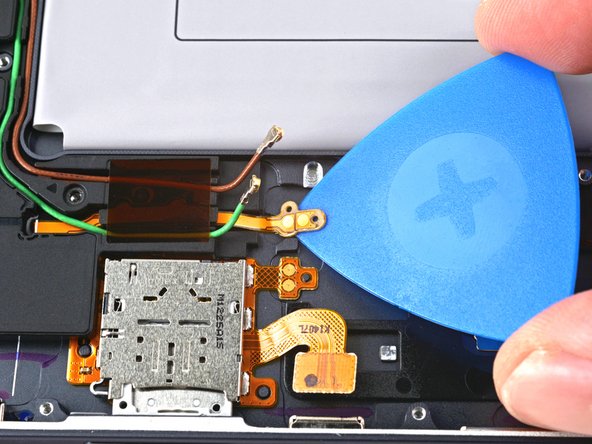
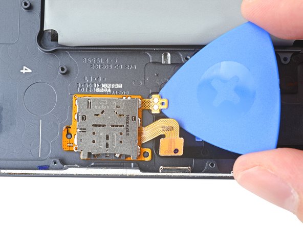
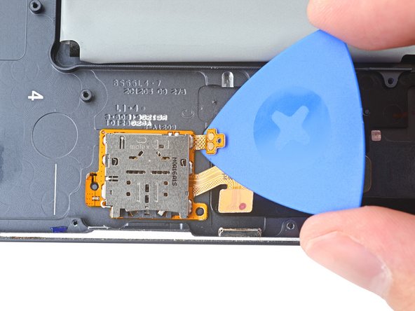
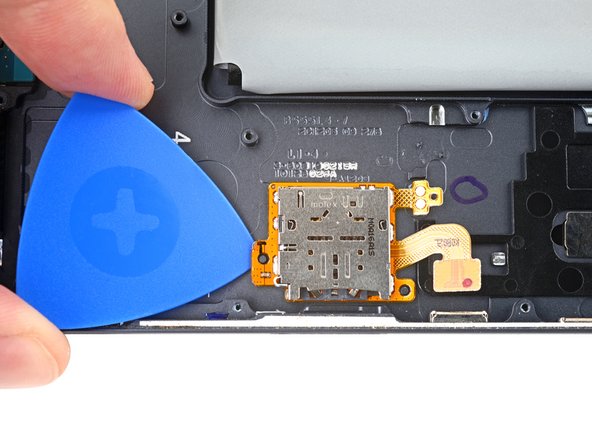
- Insert a pick between the microSD reader's connector pads and the frame.
- Pry up while slicing the adhesive to separate the pads from the frame.
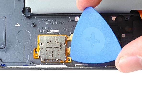
- Insert a pick between the bottom-right peg hole and the frame.
- Rotate the pick along the peg hole's perimeter to separate it from the frame.
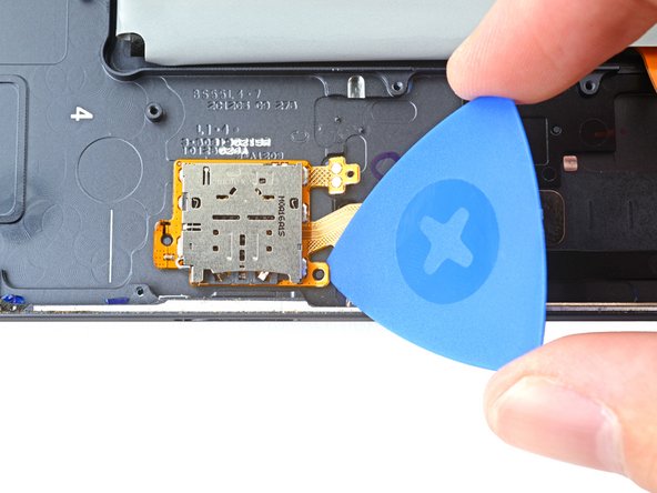
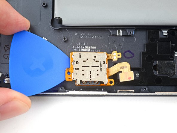
- Insert a pick between the top of the microSD reader and the frame.
- Rotate the pick around the perimeter of the microSD reader to slice the adhesive.
- At this point, the perimeter of the microSD card reader should be separated from the frame. If there's still resistance around the edges of the screen, use an opening pick to cut the adhesive again.
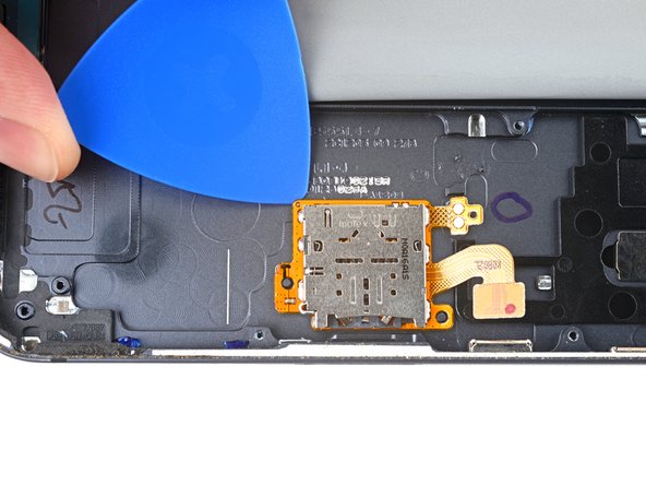
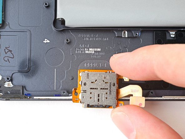
- Insert an opening pick between the bottom-left peg hole and the frame.
- Pry up with the pick to separate the microSD card reader from the frame.
- Remove the microSD card reader.
- Set the microSD card reader aside. You'll reuse it during reassembly.
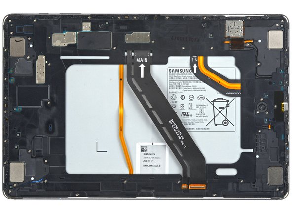
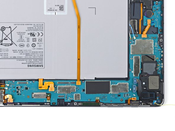
- You're now left with the battery and frame assembly.