Samsung Galaxy S22 Screen and Battery Assembly Replacement
ID: 155379
Description: Follow this guide to replace the screen and...
Steps:
- Insert a SIM eject tool, bit, or straightened paper clip into the SIM card tray hole on the bottom edge of the phone.
- Press the SIM eject tool into the SIM card tray hole to eject the SIM card tray.
- Remove the SIM card tray.
- If you accidentally inserted the SIM eject tool into a microphone hole, don't worry! You most likely didn't damage the microphone.
- Let your phone's battery to drain below 25% before starting this repair. A charged lithium-ion battery may catch fire if damaged.
- Heat an iOpener and apply it to the bottom edge of the back cover for two minutes.
- A hair dryer, heat gun, or hot plate may also be used, but be careful not to overheat the phone—the display and internal battery are susceptible to heat damage.
- While you wait for the adhesive to soften, note the following:
- There's adhesive securing the back cover around the perimeter of the frame.
- The adhesive is strongest in the bottom right and top left corners.
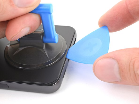
- Apply a suction handle to the back cover, as close to the bottom edge as possible.
- Pull up on the suction handle with strong, steady force to create a gap between the cover and the frame.
- If you have trouble creating a gap, apply more heat to further soften the adhesive. Follow the iOpener instructions to avoid overheating.
- Insert an opening pick into the gap.
- Slide the pick back and forth along the bottom edge to slice through the adhesive.
- Leave the pick inserted in the bottom left corner to prevent the adhesive from resealing.
- Apply a heated iOpener to the left edge of the back cover for two minutes.
- Insert a second opening pick at the bottom left corner.
- Slide the pick to the bottom of the camera bezel to slice the left adhesive.
- Only insert the pick up to 5 mm, as you may damage the antenna flex cable or the power button cable.
- Leave the pick in to prevent the adhesive from resealing.
- Heat an iOpener and apply it to the right edge of the back cover for two minutes.
- Insert a third opening pick at the bottom right corner.
- If the adhesive has resealed, insert the pick closer to the bottom edge.
- Slide the pick to the top right corner to slice the adhesive.
- Leave the pick in the top right corner to prevent the adhesive from resealing.
- Heat an iOpener and apply it to the top edge of the back cover for two minutes.
- Insert an opening pick in the gap at the top right edge.
- Slide the pick across the top edge and around the top left corner to slice the remaining adhesive.
- Only insert the pick up to 4 mm, as you may damage the rear cameras or flash.
- Grab and remove the back cover.
- If your cover is still sticking to the frame, slide an opening pick around the perimeter until the cover completely separates.
- During reassembly:
- This is a good point to power on your phone and test all functions before sealing it up. Be sure to power your phone back down completely before you continue working.
- Follow this guide to replace the back cover adhesive and install the back cover.
- Use the pointed end of a spudger to pry up and disconnect the wireless charging coil from the motherboard.
- To re-attach press connectors, carefully align and press down on one side until it clicks into place, then repeat on the other side. Don't press down on the middle. If the connector is misaligned, the pins can bend and cause permanent damage.
- Use your Phillips screwdriver to remove the six 3.5 mm-long screws securing the wireless charging coil.
- Use your Phillips screwdriver to remove the seven 3.5 mm screws securing the loudspeaker.
- Insert the pointed end of your spudger between the upper left corner of the loudspeaker and the frame.
- Pry up to unclip the loudspeaker from the frame.
- During reassembly, press around the perimeter of the loudspeaker to engage the clips.
- Grab and remove the wireless charging coil and loudspeaker from the frame.
- Do not separate the charging coil from the loudspeaker.
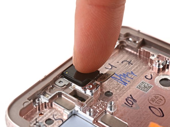
- Use the pointed end of your spudger to pry up and disconnect the battery press connector.
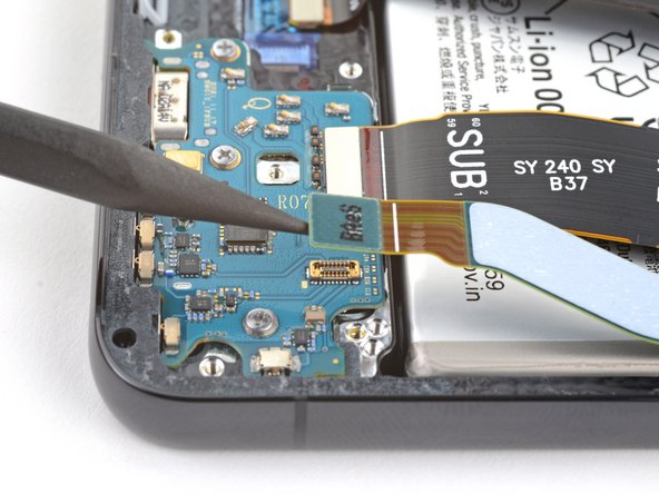
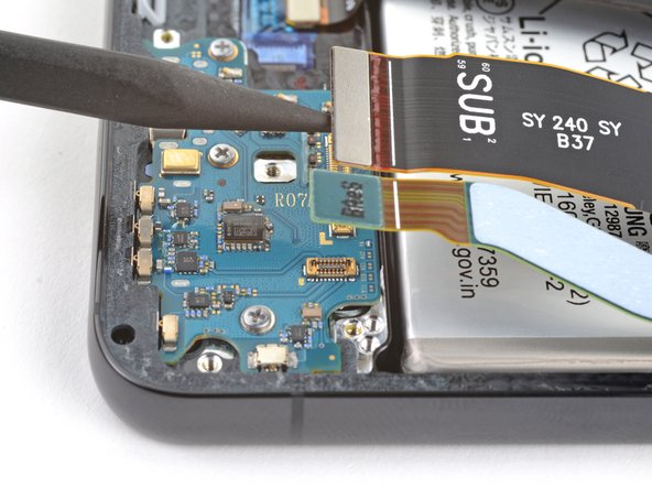
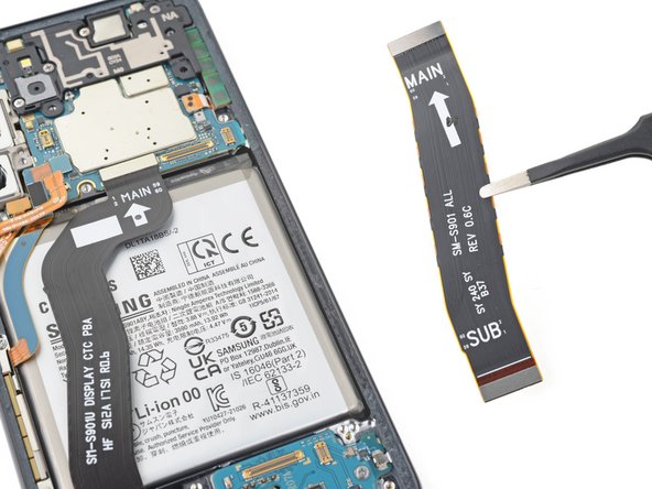
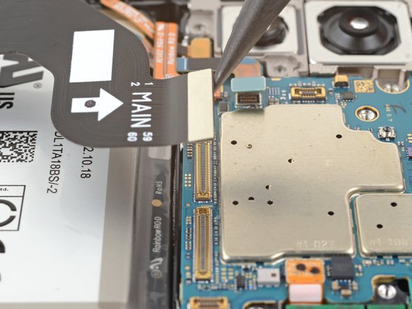
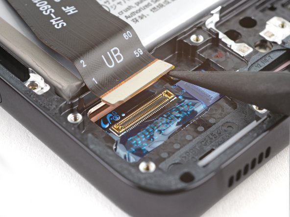
- Use the pointed end of your spudger to pry up and disconnect both interconnect cables from the motherboard.
- Use the pointed end of your spudger to pry up and disconnect both interconnect cables from the charging board.
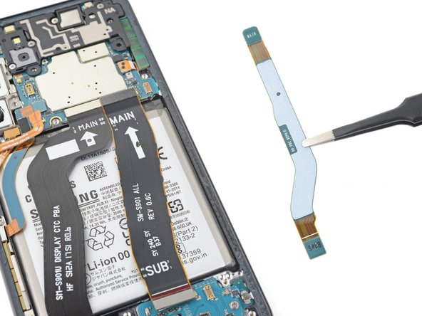
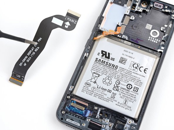
- Grab and remove the two interconnect cables from the frame.
- During reassembly, orient the cables so the "main" ends are toward the top of the phone and the "sub" ends are toward the bottom.
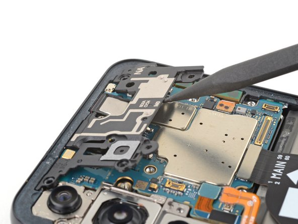
- Use your Phillips screwdriver to remove the four 3.5 mm-long screws securing the motherboard cover.
- Insert the pointed end of your spudger between the bottom of the motherboard cover and the motherboard.
- Pry up on the cover to unclip it from the frame.
- Grab and remove the motherboard cover.
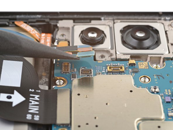
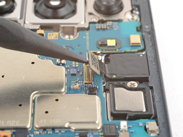
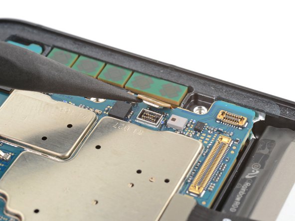
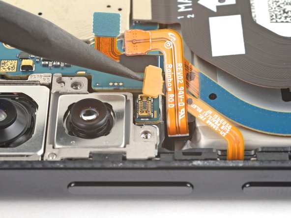
- Use the pointed end of your spudger to pry up and disconnect the left 5G mmWave antenna press connector.
- Use the pointed end of your spudger to pry up and disconnect the front-facing camera press connector.
- Use the pointed end of your spudger to pry up and disconnect the screen press connector.
- Use the pointed end of your spudger to pry up and disconnect the right 5G mmWave antenna press connector.
- Use the pointed end of your spudger to pry up and disconnect the power and volume button's press connector.
- During reassembly, make sure this cable is under the battery cable.
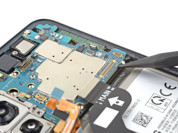
- Use your Phillips screwdriver to remove the 3.5 mm-long screw securing the motherboard.
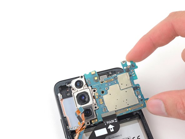
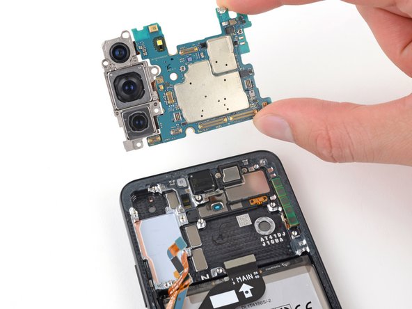
- Insert the pointed end of your spudger between the bottom right of the motherboard and the frame.
- Pry the motherboard up until you can grab it with your fingers.
- Grab the motherboard by the right edge and remove it from the frame.
- Be careful not to catch the motherboard on any loose cables.
- During reassembly, be sure the cables are above the motherboard when reinserting it.
- Use your Phillips screwdriver to remove the three 3.5 mm-long screws securing the charging board.
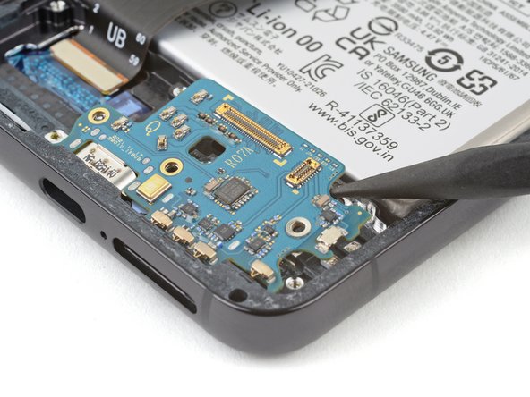
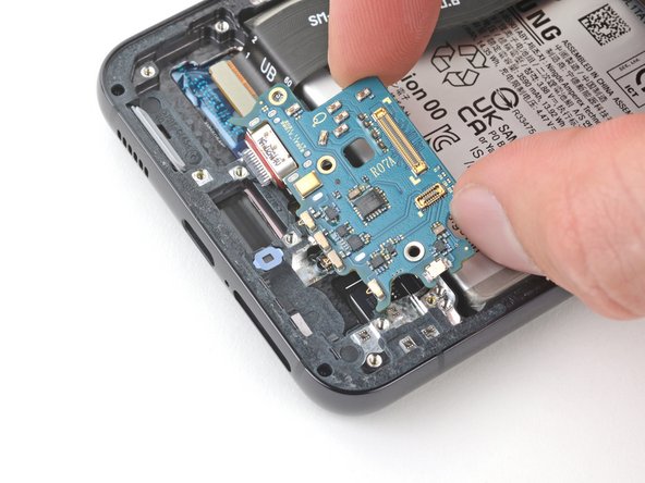
- Insert the pointed end of your spudger between the top right of the charging board and the frame.
- Pry the charging board up from its recess until you can grab it with your fingers.
- Grip the charging board by its corners and slide it out of its recess in the frame.
- Remove the charging board.
- During reassembly, reinsert the charging board at a downward angle to guide the USB-C port into its recess.
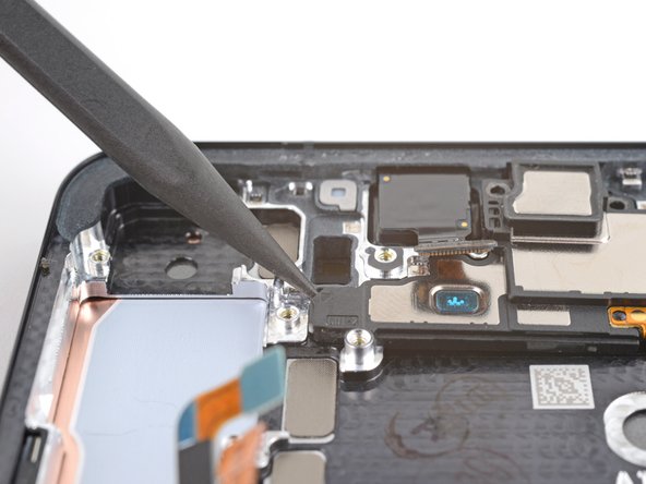
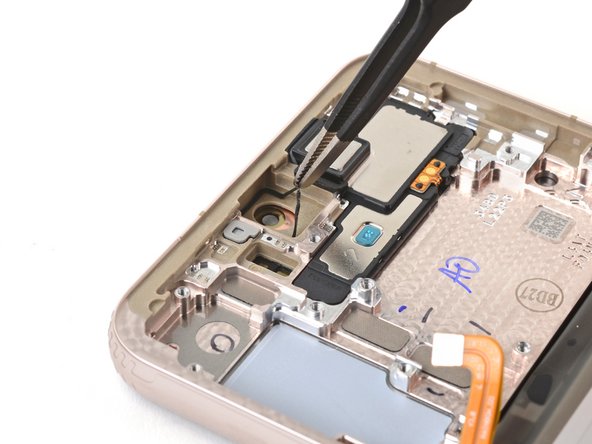
- Use your Phillips screwdriver to remove the two 2.9 mm-long screws securing the earpiece speaker.
- Insert the pointed end of your spudger under the left edge of the earpiece speaker.
- Pry up to unclip the earpiece speaker from the frame.
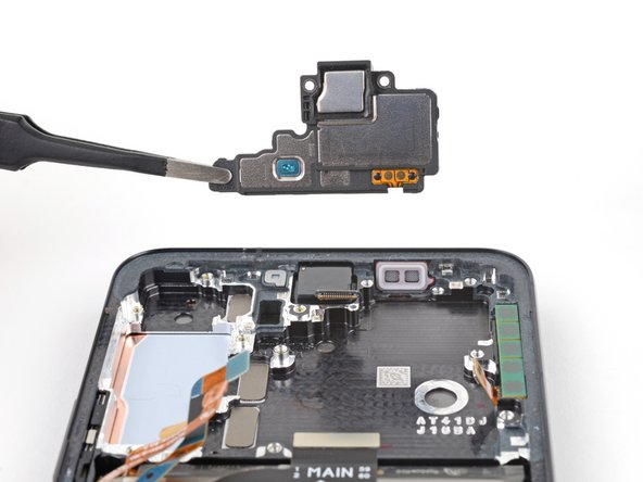
- Grab and remove the earpiece speaker.
- Use your Phillips screwdriver to remove the two 3.5 mm-long screws securing the lower 5G mmWave antenna.
- Insert the pointed end of your spudger between the lower screw mount of the antenna bracket and the frame.
- Pry up on the bracket until you can grab it with blunt nose tweezers or your fingers.
- Remove the lower 5G mmWave antenna.
- Before reinstalling the lower 5G mmWave antenna, replace the bracket with a new one. If you don't have a new bracket, skip this step.
- Remove the antenna and connector from the old bracket.
- Remove the L-shaped adhesive liner from your new bracket.
- Place the antenna in the bracket's recess with the connector fed underneath the longer screw mount.
- Remove the thin adhesive liner on the outside of the bracket before installing it in the frame.
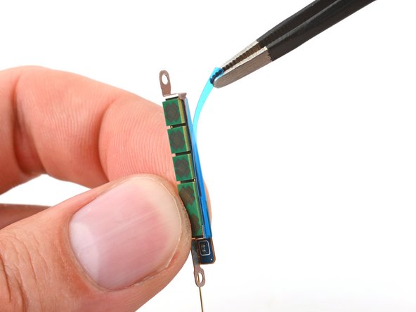
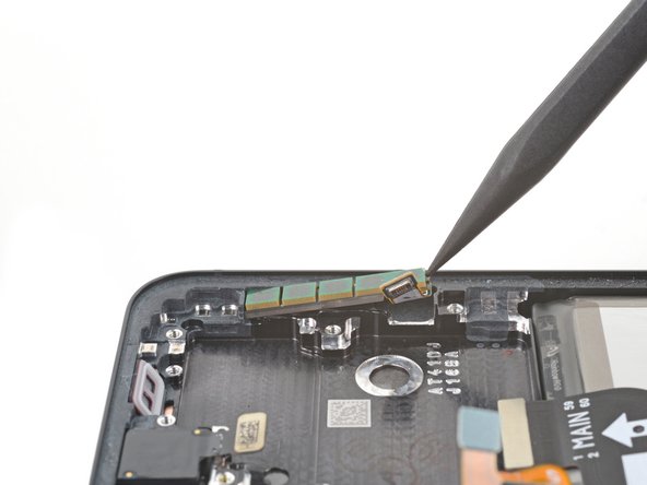
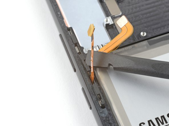
- Insert the pointed end of your spudger in the gap between the upper 5G mmWave antenna and the frame
- Pry the antenna out of its recess until you can grab it with your fingers or blunt nose tweezers.
- If the antenna feels stuck, apply a heated iOpener for two minutes to soften the adhesive.
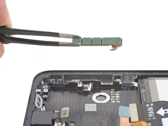
- Remove the upper 5G mmWave antenna.
- Replace the adhesive on the upper 5G mmWave antenna before reinstalling it. If you don't have replacement adhesive, reuse your old one or use custom-cut adhesive.
- Remove the existing adhesive from the antenna with blunt nose tweezers or your fingers.
- Remove the clear liner from your new adhesive.
- Apply the new adhesive to the bottom of the antenna, with its round end farthest from the connector.
- Remove the green liner from the adhesive before reinstalling the antenna in the frame.
- Heat an iOpener and apply it to the top of the screen for two minutes.
- A hair dryer, heat gun, or hot plate may also be used, but be careful not to overheat the phone—the display is susceptible to heat damage.
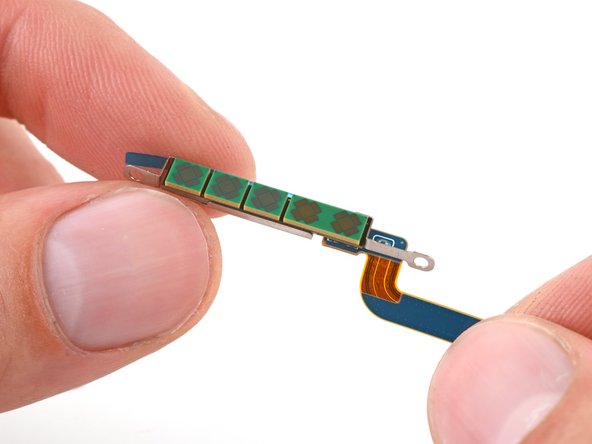
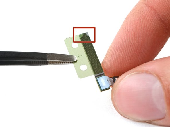
- The adhesive securing the camera is very strong. Work slowly and apply more heat if the camera feels stuck. Avoid separating the circuit board from the camera, like this.
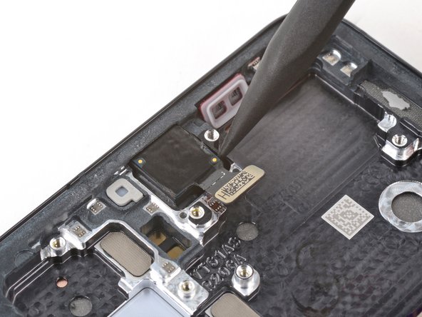
- Use the pointed end of your spudger to pry the front-facing camera from its recess.
- If the camera doesn't loosen, use your SIM card eject tool to scrape away the epoxy surrounding the camera.
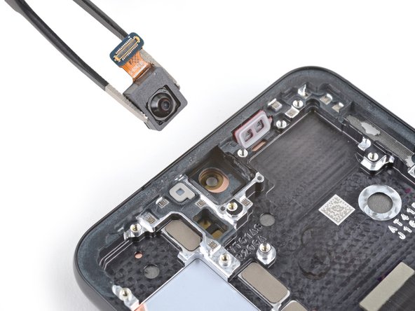
- Use a pair of blunt nose tweezers to grab and remove the front-facing camera from its recess.
- During reassembly, prepare your new frame for the front-facing camera:
- Remove the black adhesive liner from the front-facing camera recess.
- Peel and remove the foam liner from the new frame.
- This liner isn't necessary for the repair.
- Before installing the front-facing camera, replace the adhesive in the frame:
- Remove the clear liner from the front-facing camera adhesive.
- Place the adhesive in the camera recess with its pull tab facing right.
- Remove the blue adhesive liner using its pull tab.
- Insert the front-facing camera into its recess in the frame and apply pressure to secure it.
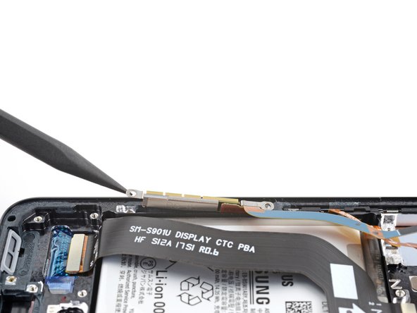
- Use the pointed end of your spudger to pry up and disconnect the display cable press connector.
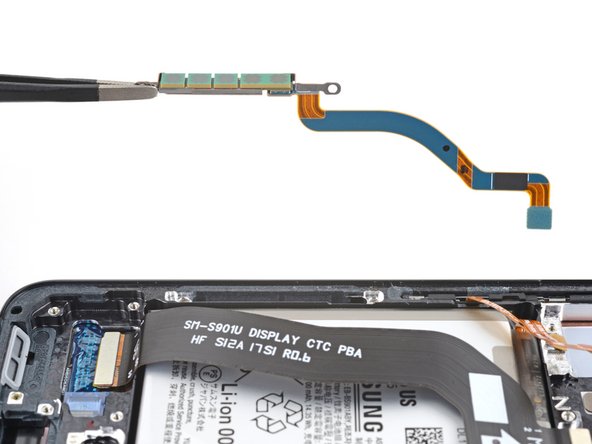
- Grab and remove the display cable from the frame.
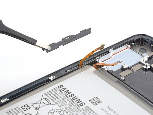
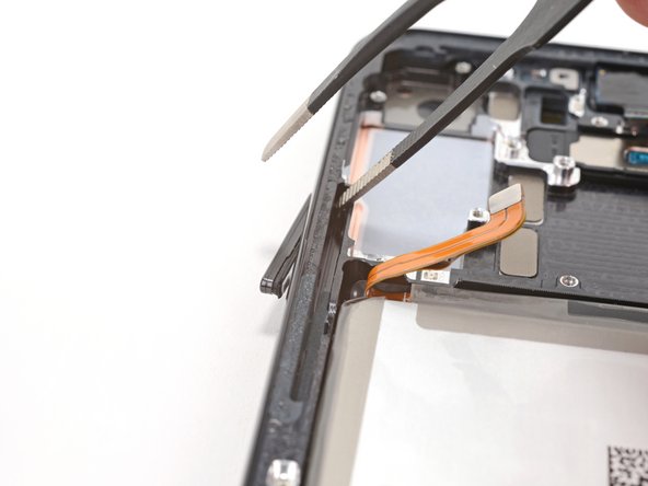
- Insert the corner of your spudger in the tab on the power and volume button bracket.
- Twist the spudger upward to pry and loosen the bracket from its recess in the frame.
- During reassembly, press each button to make sure they "click." They should have the same sound and feel as before disassembly.
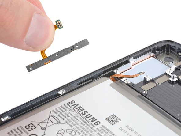
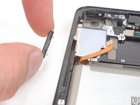
- Use blunt nose tweezers or your fingers to grab and remove the power and volume button bracket.
- The button pad may come out with the bracket.
- Use your fingers to grab and remove the button pad.
- During reassembly, insert the button pad first. Then, insert the bracket against the back of the button pad. Together, they look like this.
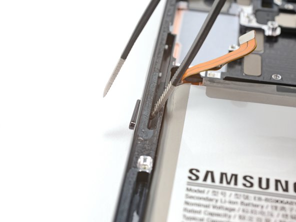
- Insert one arm of your blunt nose tweezers into the power button's recess.
- Press against the power button's peg to separate it from the frame enough so you can grab the button with your fingers.
- If blunt nose tweezers don't reach deep enough into the recess, use the bent tip of a paperclip or a similarly-shaped object.
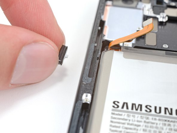
- Use your fingers to grab and remove the power button.
- Insert one arm of your blunt nose tweezers into the volume button's recess.
- Press against both of the volume button's pegs to separate them from the frame enough so you can grab the buttons with your fingers.
- If blunt nose tweezers don't reach deep enough into the recess, use the bent tip of a paperclip or a similar-shaped object.
- Use your fingers to grab and remove the volume buttons.
- You're now left with the screen and battery assembly.
- Compare your new replacement part to the original part—you may need to transfer remaining components or remove adhesive backings from the new part before you install it.