Replacement thermal fuse on bread machine
ID: 155414
Description: Description of the disassembly and diagnostic...
Steps:
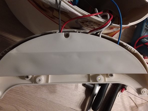
- Place the cover in an upright position
- Lift it out of its joint
- Remove the 4 shutters from the control panel with a very thin screwdriver. This can be difficult or even impossible.
- Use a forest as a last resort to start a drill.
- Catch each shutter with the forest
- With a PH2 screwdriver remove the 4 screws dia 3 x 13
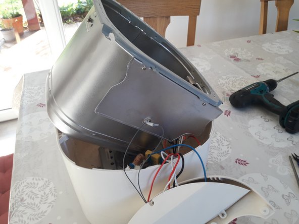
- Lift and tilt the panel forward
- With a PH2 screwdriver remove the 4 upper screws dia 4.2 x 9.5
- With a PH2 screwdriver remove the 4 lower screws M 4 x 6
- Lift the crankcase
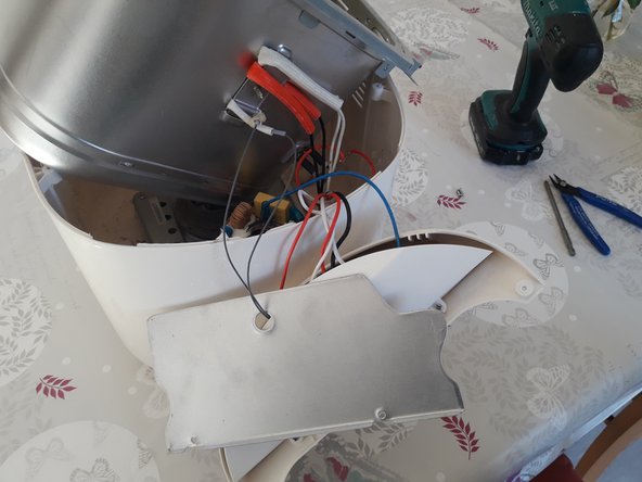
- With a PH2 screwdriver remove the 2 screws dia 4.5 x 9.3
- Tilt and slide the screen down along the two wires of the temperature probe
- This gives you access to the environment of the two thermal fuses
- The purpose is to deposit the sheet metal flange that holds the two fuses (two large white and red textile sheaths) and the probe (small white sheath)
- The maintenance of this flange is ensured by a single sheet metal screw whose head is accessible inside the thermal housing.
- Use a small ratchet wrench or a short screwdriver with PH2 bit, and continue by hand.
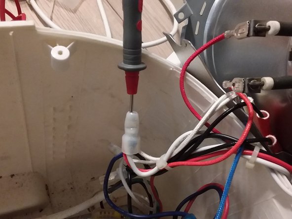
- The absence of a power supply requires a diagnosis. The electrical test can be facilitated by opening the back of the splices with a cutting clamp.
- Open only the strict minimum to be able to pass the touch point of the multimeter.
- Open only the strict minimum to be able to pass the touch point of the multimeter.
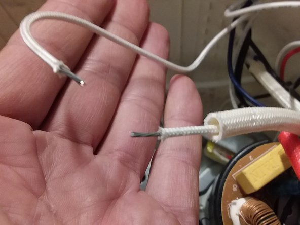
- In our case, using the continuity function of the multimeter, it is the thermal fuse protected by the white sheath that is found to fail.
- Slide the textile sheath to make the fuse and its set rings appear.
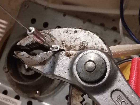
- Cut the wire at the level of the two rings
- Bare on a length corresponding to those of new rings
- Set up the three elements and crimp firmly.
- Check the electrical continuity
- Replace the textile sheath.