Commercial 8 Quart Bowl-Lift Stand Mixer - Powertrain/Motor Replacement
ID: 157888
Description: The powertrain assembly is comprised of the...
Steps:
- Before starting ANY repair/disassembly of the mixer, make sure it is fully unplugged from the electrical outlet.
- If this mixer is being used in a commercial environment, a LOTO tag can be affixed via the hole on one of the prongs on the mains plug to prevent accidental activation.
- The speed/motor control assembly contains capacitors which can retain their charge for an indefinite amount of time. These capacitors can present a significant and potentially fatal shock hazard.
- Using a #2 Philips Screwdriver, remove the screw which holds on the trim band.
- Remove the trim band.
- Remove the four screws (circled in yellow, two on each side) using a #2 Philips Screwdriver
- Remove the motor housing by lifting it straight up.
- Place a couple dish towels or other soft materials on the base to protect it from any potential impact.
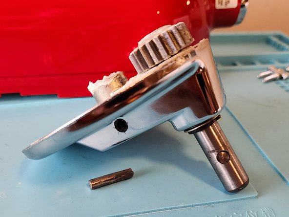
- Disconnect the planetary from the motor drive shaft by removing the retaining pin (circled in yellow). You can do this with a hammer and either a pin punch or a Torx T15 screwdriver. Simply hammer the punch/screwdriver on the pin until it comes out the other side.
- If the planetary assembly doesn't fall out, you might have to give it a firm pull straight down to remove it.
- Using a #2 Phillips Screwdriver, remove the four screws (circled in yellow).
- When removing the last screw, make sure to place your hand under the planetary gear as it is heavy and will fall out immediately.
- There are two motor support brackets: one in front, one back (shown in the first image)
- Each bracket is attached to the motor by two screws (one on each side).
- Using a #2 Phillips screwdriver, remove the four screws (circled in yblue in the second and third images) which attach the two motor support brackets.
- Take care to place your hand under the support bracket when removing the second screw as they will fall out and could damage the finish.
- Disconnect the motor power cable by depressing the locking tab (circled in yellow) while pulling the connector apart.
- Do not attempt to remove the hall effect sensor, the cord which attaches back by the fan, as it is much more easily removed at a later step.
- Using a #2 Philips screwdriver, remove the four screws (indicated in yellow, two on each side) attaching the powertrain/motor to the mixer body.
- Take care to support the motor as it is no longer connected to the mixer body and could damage the circuit board underneath
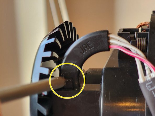
- Remove the hall effect sensor from its mount by pressing down on the tab indicated in the first picture and sliding it out.
- Now that the powertrain/motor is fully disconnected from the mixer, remove it and place it to the side.
- Begin the reassembly process with the new powertrain/motor