Arlo Ultra 2 Camera Lens Replacement
ID: 158561
Description: If the camera lens on your Arlo Ultra 2 is not...
Steps:
- Press the button on the bottom of the camera to release the housing.
- Pull the white housing off the camera.
- Pull the white cube shaped battery from the back to remove it from camera.
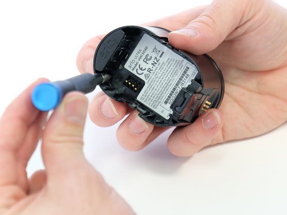
- Use a Phillips #0 screwdriver to remove the four 20.0 mm screws from the battery cavity. They are found in each corner.
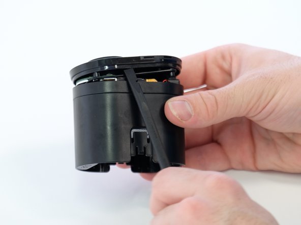
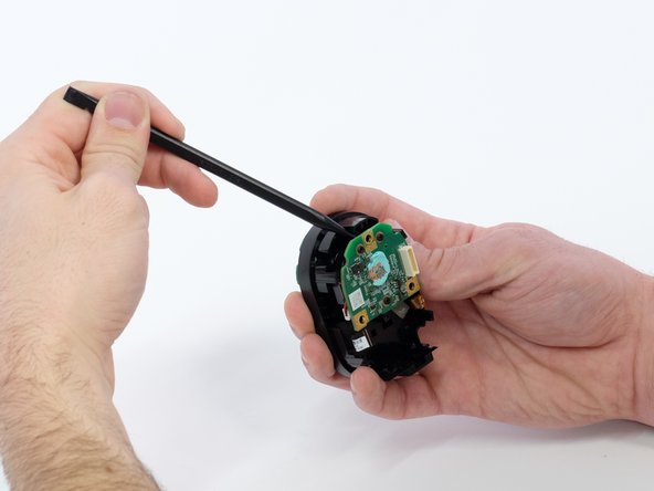
- Using the spudger, loosen and remove the camera faceplate.
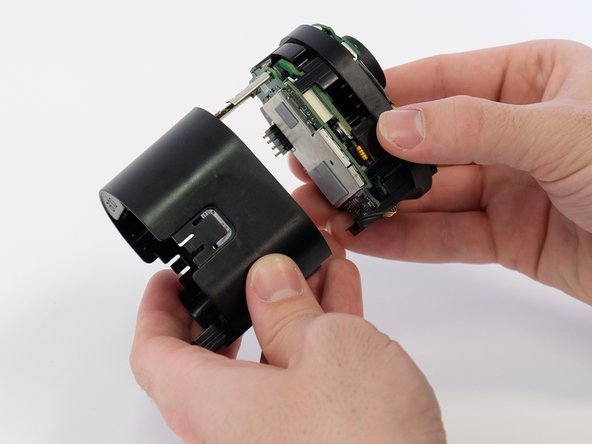
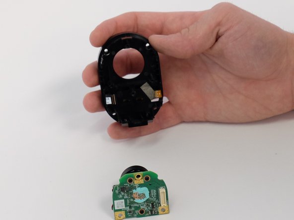
- Using the spudger, loosen and remove the back casing to expose the camera hardware.
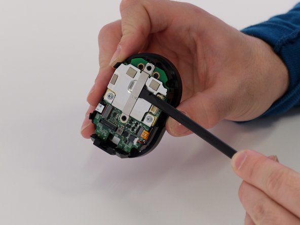
- Very gently, pry the circuit boards apart from the white connector, removing the upper circuit board.
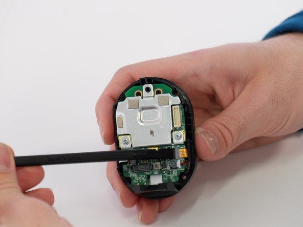
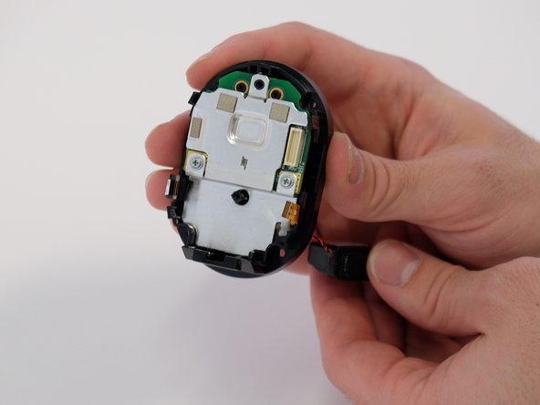
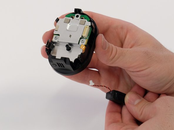
- Use a Phillips #00 screwdriver to remove two 5.0 mm screws from the metal bracket.
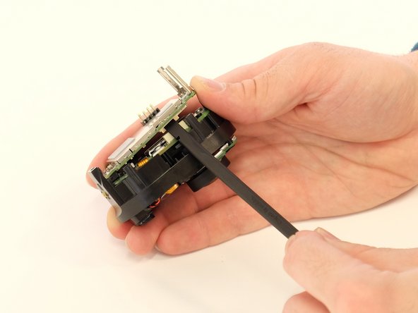
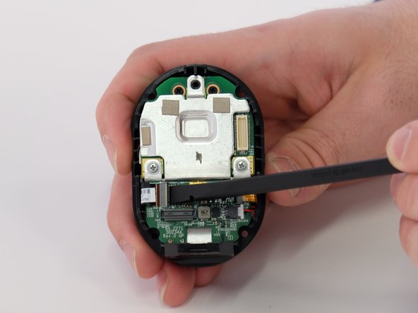
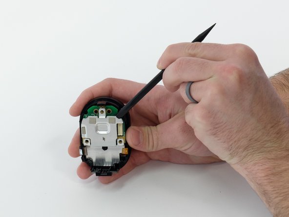
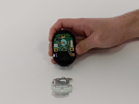
- Use a spudger to separate the long metal bracket.
- There is an arrow etched into the bracket. It points towards the top of the camera. This is important when reassembling the camera.
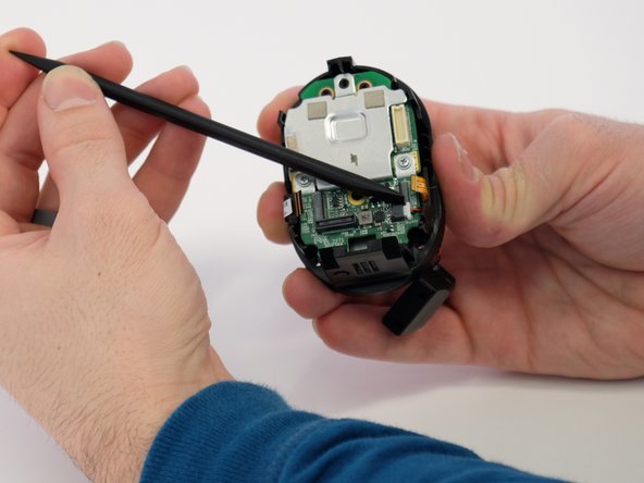
- Use the tip of a spudger or your fingernail to flip up the small locking flap on each ZIF connector. Then, you can safely pull the cables out.
- Be sure to pry up on the hinged flap, not the connector socket.
- Use a spudger to carefully push on each side of the speaker cable connector until it's out of its socket.
- Remove the small green circuit board.
- Feed the speaker cable through the opening to remove the speaker.
- Use a Phillips #00 screwdriver to remove the two 5.0 mm screws from both sides of the metal plate.
- Pry the metal plate away from circuit board underneath.
- There is a small amount of blue putty in between the metal plate and the circuit board.
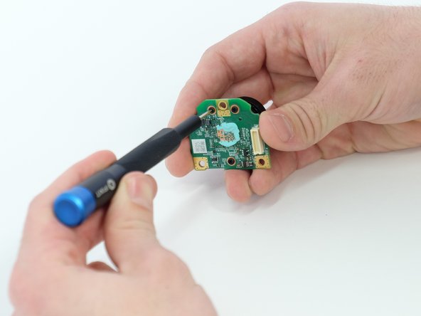
- Use a spudger to remove the entire green circuit board with lens attached.
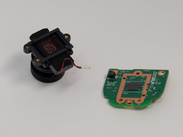
- Use a Phillips #00 screwdriver to remove three black 5.0 mm screws from back of the circuit board.
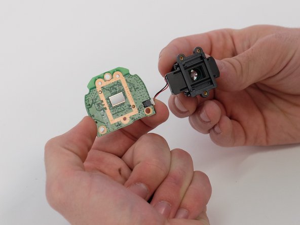
- Separate the lens from the circuit board.
- There is a small cord connecting the lens and circuit board.
- Use a spudger to carefully push on each side of the white cable connector to remove it from the socket and separate the camera lens from the board.
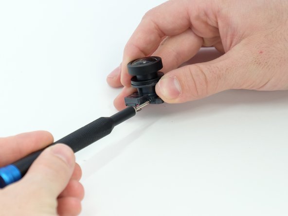
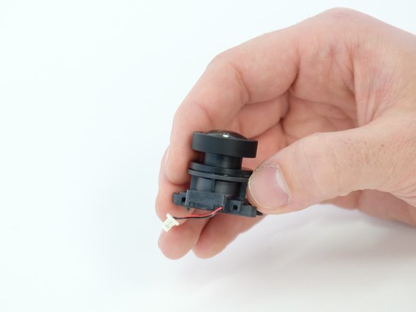
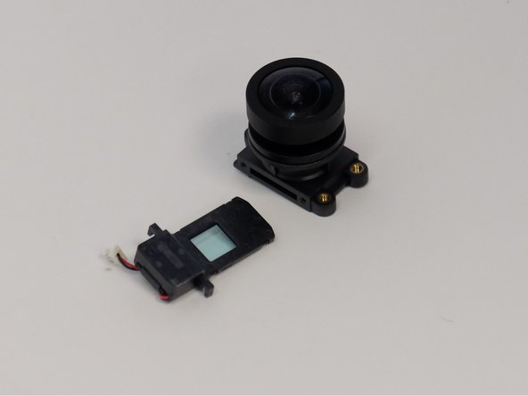
- Use a Phillips #00 screwdriver to remove the two 4.0 mm screws from the side of the lens body.
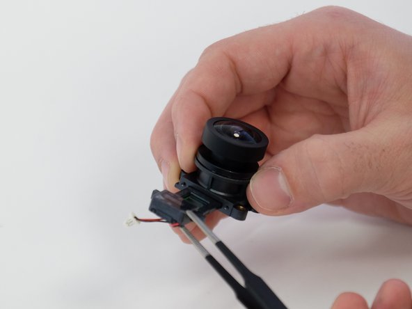
- Use the blunt tweezers to remove the focus motor control insert from the main lens body.