Scholl Roll Pedicure Roller Teardown
ID: 160447
Description:
Steps:
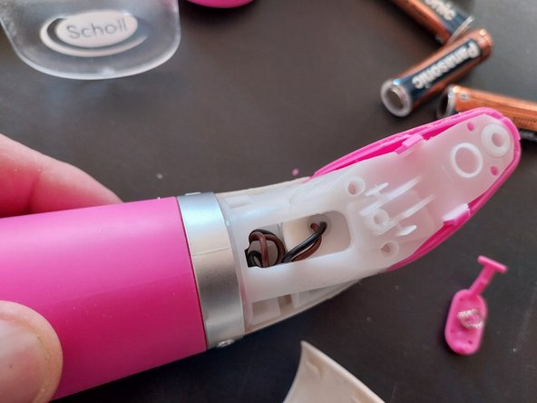
- Teardown of a Dr. Scholl Velvet Smooth Pedi, this device is not built with the expectation that it can be disassembled, it is a typical disposable device, this is due to the fact that the 2 white side covers are glued along the line that joins them, so to disassemble it, you have to pry and force the adhesive to break
- Photo 1: The entire surface held with adhesive is indicated; there are no screws.
- Photo 2: For the teardown, use a small flat-head screwdriver to gently pry, starting from the central notch toward the handle, on both sides of the cover. First, remove the cover that sits on top of the second cover.
- Photo 3: Once the first cover is removed, proceed in the same way with the second. BE VERY CAREFUL WITH THIS 2ND ONE, as the motor gears rest against it.
- Views of the disassembled cover 1, this corresponds to the file extraction button.
- Teardown of cover 2 by proceeding in the same way as with cover 1; be careful, as this one holds the side gears in place.
- Cover 2 secures the other side of the gears, SO WE MUST BE VERY CAREFUL WHEN HANDLING IT. As a tip, it is best to secure the gears with tape so they do not fall out.
- Pry up the center U-bracket, which gives us access to the motor.
- Remove the motor by prying on the side near the cables.
- Underneath the motor, there are 3 screws that secure the battery holder assembly.
- Remove the screws if you need to access the battery holder and switch connections.
- Once the 3 machine screws are loosened with the help of universal pliers, we can remove the battery holder + switch.
- CAUTION: the wires do not allow for full removal as they are connected to the universal motor at the other end. They must be desoldered from the universal motor.
- This machine had a COMBINED FAILURE; the negative wire on the battery holder was broken and the universal motor was damaged. In the end, it was not possible to repair it.
- Photo 1: View of the battery holder removed after having disconnected the wires from the motor; we can see that one of the wires is broken.
- Photo 2: View of the broken, DEGRADED, BLACK wire; it has absorbed water or moisture through capillary action and is unsolderable, with the copper blackened.
- The connection to the battery holder was loose, which was the cause of the breakage.
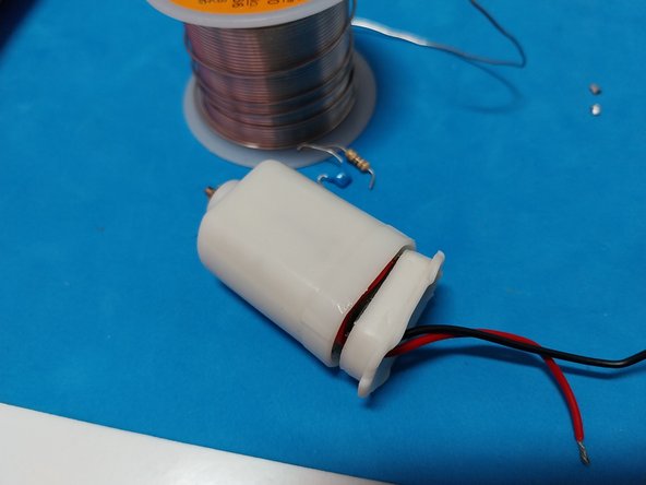
- Motor view AS A TIP: BEFORE TRYING TO SOLDER THE MOTOR, test it outside the device by applying 6V; in this case, the machine had a combined failure (Broken Cable and Faulty Motor). After the entire process, the motor was faulty; it gave no ohm reading with a multimeter.
- Comparison of the SPECIFIC MOTOR FOR THIS MACHINE with a similar standard motor; although the pinion matches, the standard motor cannot be installed.
- Photo 1: Other pinion models that could not be used.
- Photos 2 and 3: Attempt to install the standard motor; it is not compatible as the pinion does not properly reach the gears.
- The standard motor, despite fitting into the mount, does not protrude enough, so an unsuccessful attempt is made to modify the mount by removing plastic from it.
- Work with a Dremel removing material from the inside of the support did not result in any improvement, therefore IT CANNOT BE INSTALLED.
- Machine not repaired, the cost of a replacement motor exceeds more than 50% of the cost of a new machine.