HTC Vive XR Elite Headstraps Replacement
ID: 161400
Description: Follow this guide to replace the headstraps in...
Steps:
- Before starting this repair, discharge the batteries in your headset below 25%. A charged battery may leak dangerous chemicals or catch fire if damaged.
- Playing Half Life: Alyx will do the trick!
- The Vive XR Elite has a proximity sensor that puts the headset in standby mode to save battery when it isn't in use. To drain the battery faster you'll need to use the headset.
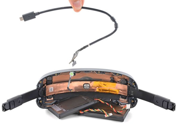
- Disconnect the USB-C power cable.
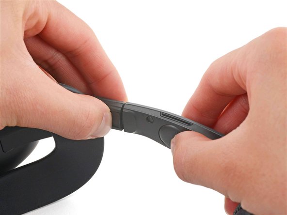
- Press the release button on the right battery cradle temple slot.
- Pull the battery cradle away from the right temple slot to disconnect it.
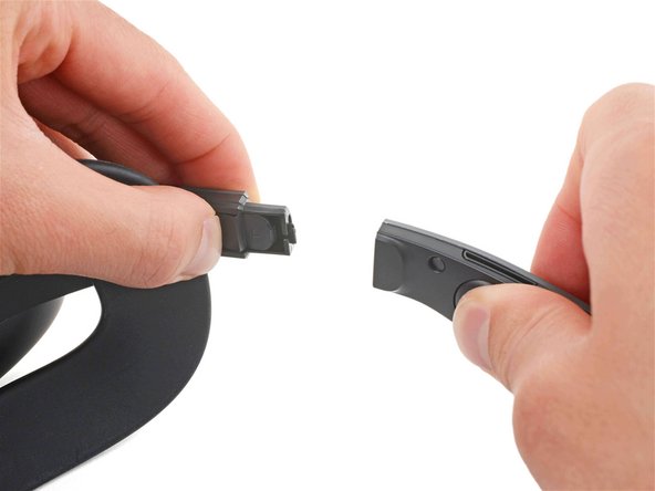
- Repeat the previous step for the left temple slot.
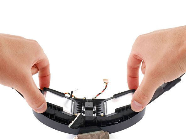
- Separate the headset and battery cradle.
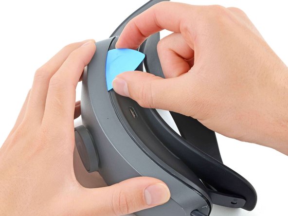
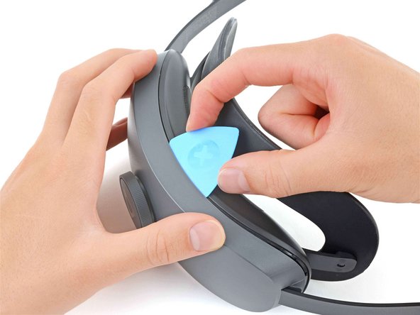
- Insert a long edge of an opening pick in the gap between the two halves of the battery cradle, near the USB-C cable.
- Slide the opening pick along the top edge of battery cradle to release its plastic clips.
- Flip the battery cradle over.
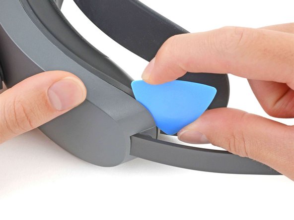
- Insert the long edge of an opening pick in the gap between the two halves of the battery cradle.
- Slide the opening pick along the bottom edge of battery cradle to release its plastic clips.
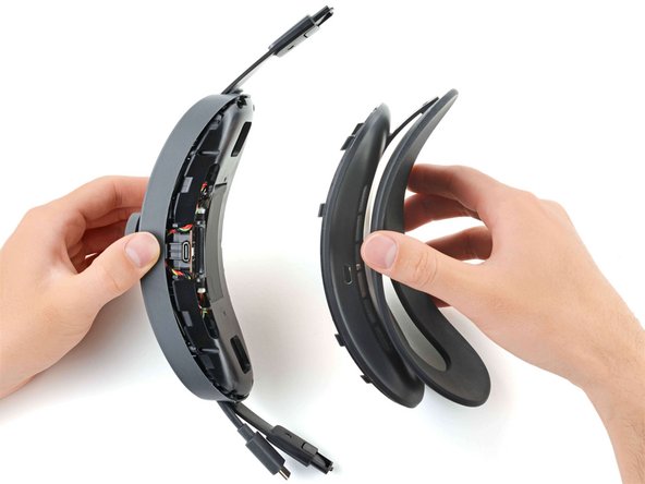
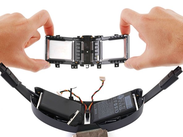
- Pull apart the two halves of the battery cradle to completely separate them.
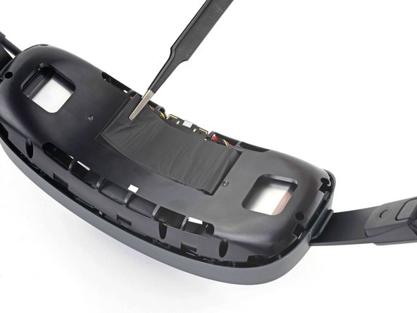
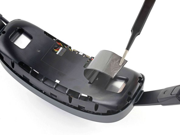
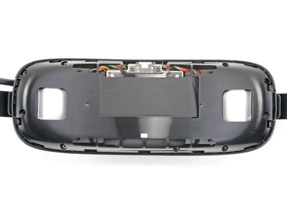
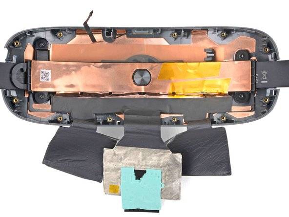
- Use tweezers to peel back the graphite thermal tape covering the inner plastic frame.
- If the tape tears a little, don't worry! During reassembly, stick it back in its original place as if it were still one piece
- Use a T5 Torx screwdriver to remove the nine screws securing the inner plastic frame:
- Five 11.8 mm-long screws
- Three 5.6 mm-long screws
- One 5.6 mm-long screw
- This screw is covered by a piece of black plastic tape. Use tweezers to remove it before unscrewing.
- Throughout this repair, keep track of each screw and make sure it goes back exactly where it came from.
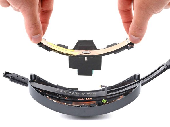
- Remove the inner plastic frame, making sure to thread the graphite thermal tape through it.
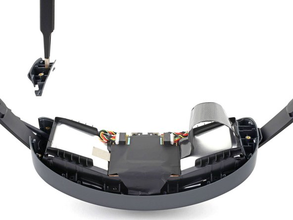
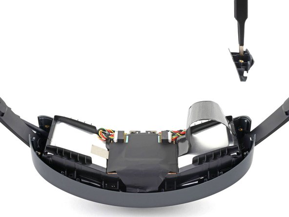
- Use a T5 Torx screwdriver to remove the two 5.6 mm-long screws securing the headstrap clips.
- Use tweezers to remove the left and right headstrap clips.
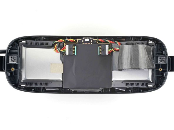
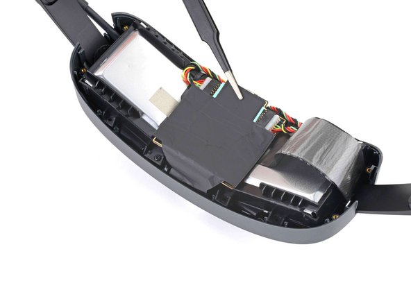
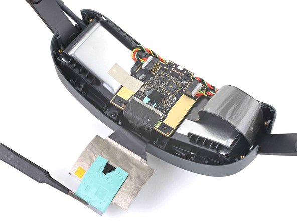
- Use tweezers or your fingers to peel back the thermal pad covering the battery board.
- Work slowly to avoid tearing the thermal pad.
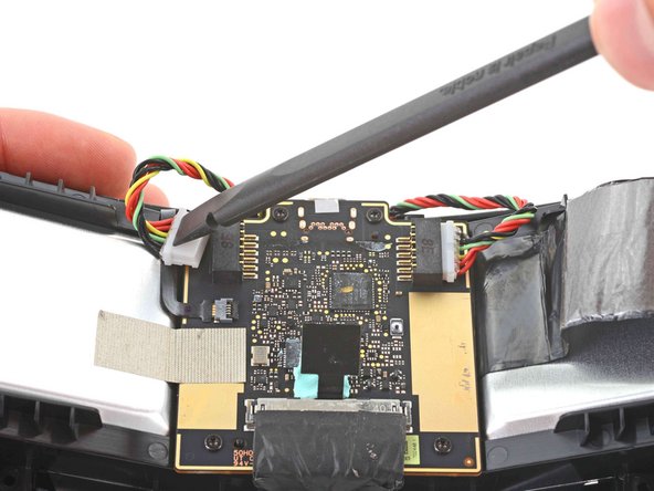
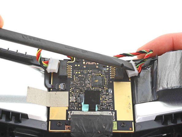
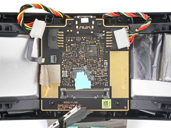
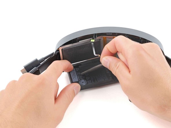
- Use the flat end of a spudger to push the left and right battery cell connectors out of their respective sockets.
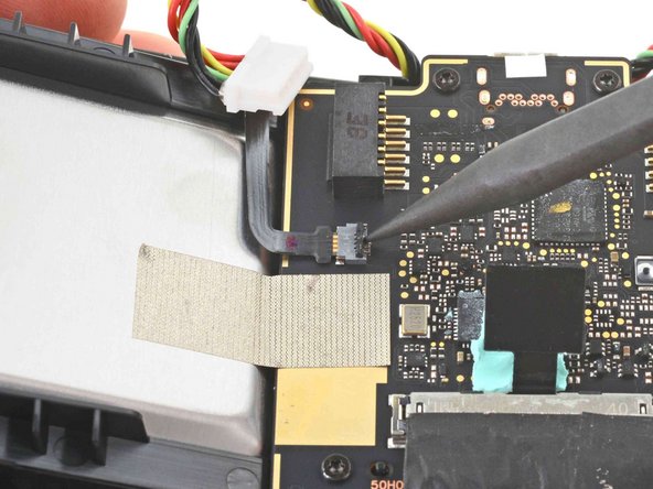
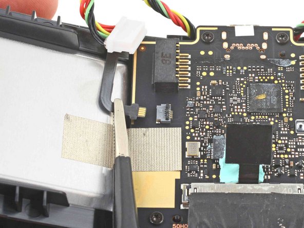
- Use the point of a spudger to flip up the locking flap on the power LED ZIF connector.
- Use tweezers or your fingers to disconnect the power LED cable.
- During reassembly, slide the cable into the connector and close the locking flap. If the cable is getting stuck, gently remove it and realign it before trying again.
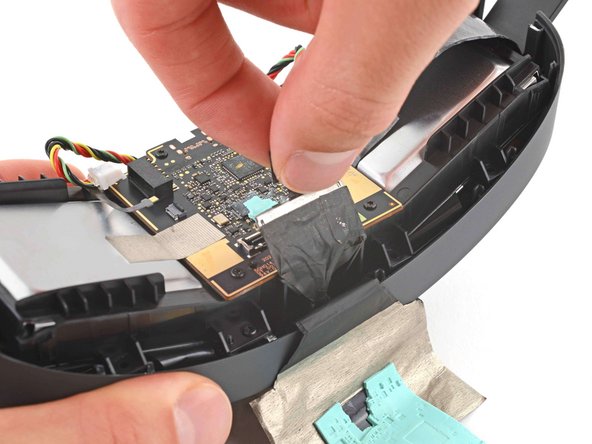
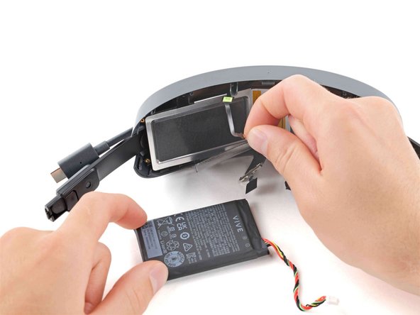
- Pull the black tab straight up on the USB-C power cable to disconnect it.
- During reassembly, align the cable directly over the connector and press straight down to reconnect it.
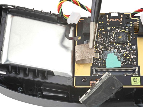
- Use tweezers or your fingers to peel the conductive tape away from the front metal battery enclosure.
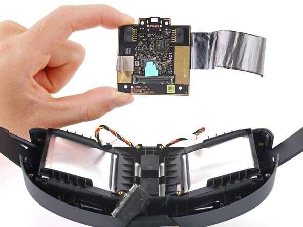
- Use a T5 Torx screwdriver to remove the four 4.1 mm-long screws securing the battery board.
- Remove the battery board.
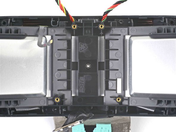
- Use a T5 Torx screwdriver to remove the three screws securing the front metal battery enclosure:
- Two 11.8 mm-long screws
- One 4.8 mm-long screw
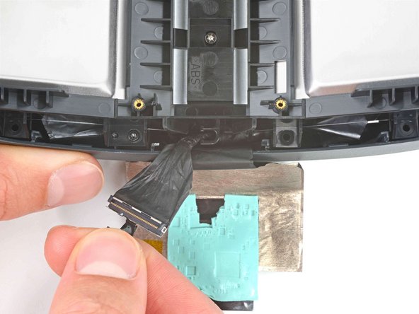
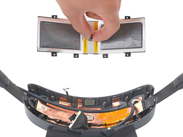
- Slide the USB-C power cable to the left to unclip it.
- Remove the front metal battery enclosure.
- Stand the battery cradle upright so the battery cells can fold flat on your work surface.
- Don't try to fully remove the batteries yet, as they're still attached to the cradle with graphite thermal tape.
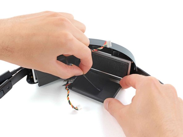
- Peel off the graphite thermal tape covering the right battery cell.
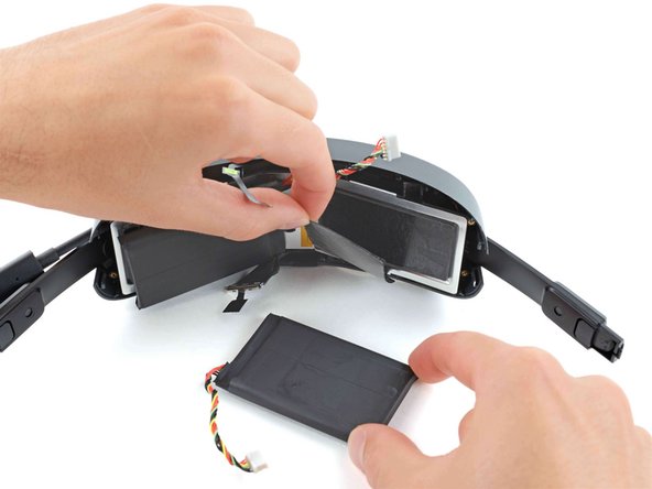
- Remove the right battery cell.
- Repeat the previous step for the left battery cell.
- Grip the center plastic screw spacer with your fingers.
- Remove the rear metal battery enclosure.
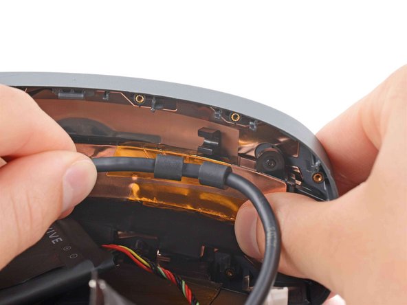
- Hold one end of the USB-C power cable and pull it straight back to unclip it.
- Remove the USB-C power cable.
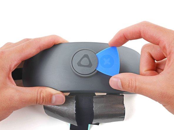
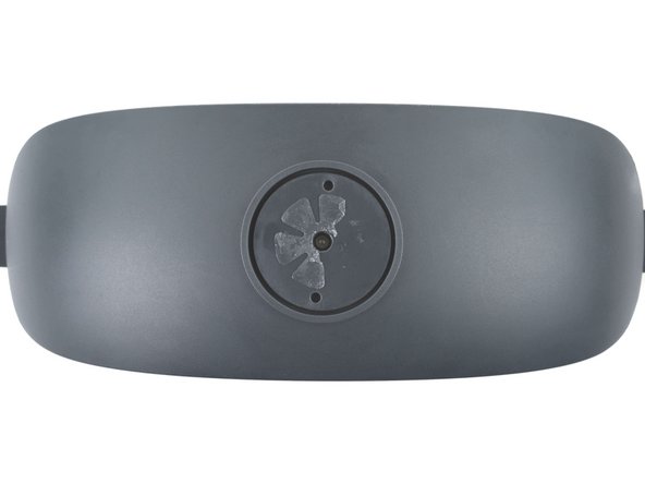
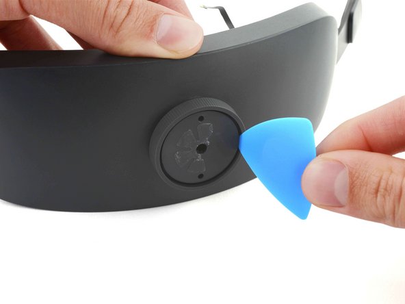
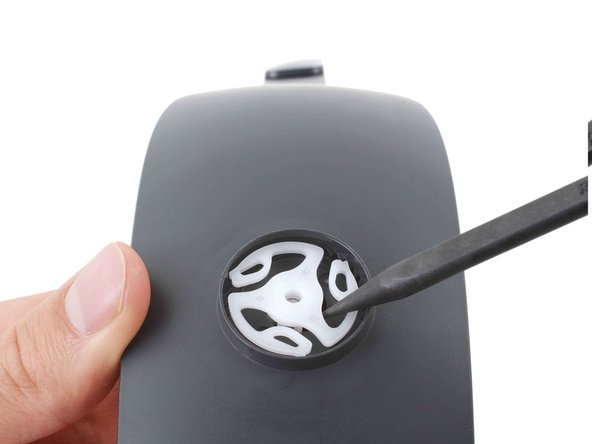
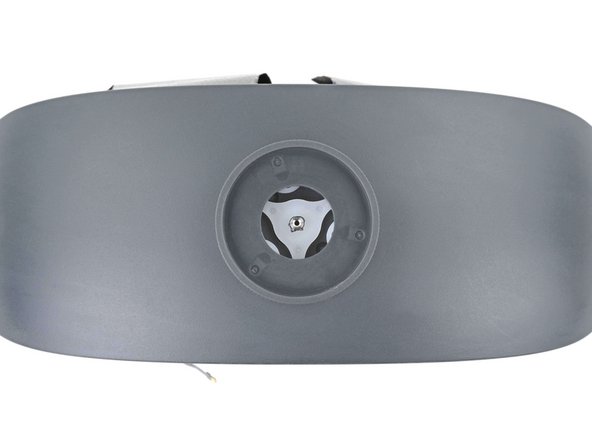
- Insert an opening pick under the adjustment dial faceplate.
- Pry up to separate the adhesive securing the faceplate.
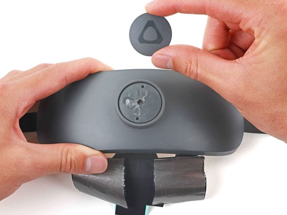
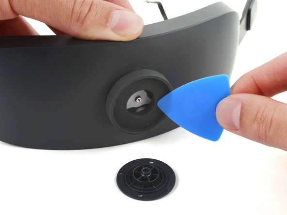
- Remove the faceplate.
- During reassembly, clean off any old adhesive using high-strength (>90%) isopropyl alcohol and a lint-free cloth. Use Tesa Tape to secure the faceplate to the adjustment dial.
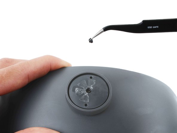
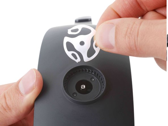
- Use tweezers to remove the plastic tape covering the adjustment dial screw.
- Use a Torx T5 screwdriver to remove the 3.8 mm-long screw securing the adjustment dial.
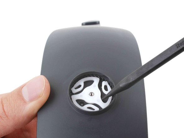
- Insert an opening pick between the adjustment dial and the screw spacer.
- Pry the screw spacer away from the adjustment dial to remove it.
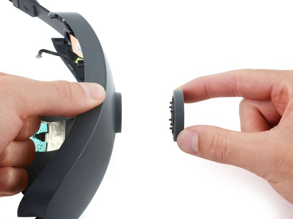
- Pull the adjustment dial straight off the cradle and remove it.
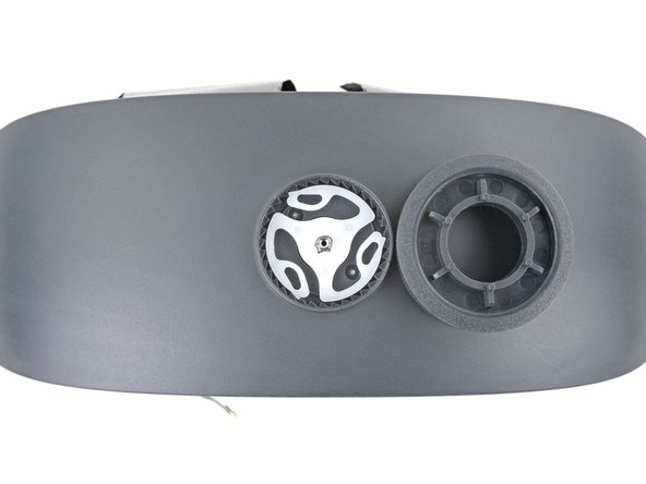
- Use the point of a spudger to pry up the center of the sprocket.
- Remove the adjustment dial sprocket.
- Adjust the headstraps so they're fully retracted into the cradle.
- Insert the sprocket so its teeth fully mesh with the teeth in the socket.
- During reassembly, make sure three pegs on the adjustment dial are inserted into the three cutouts on the sprocket:
- Three adjustment dial pegs
- Three sprocket cutouts
- Use the molding marks to align the dial over the cutouts on the sprocket.
- You'll know the dial is installed correctly when it easily turns counterclockwise and clicks when turned clockwise.
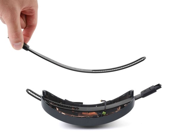
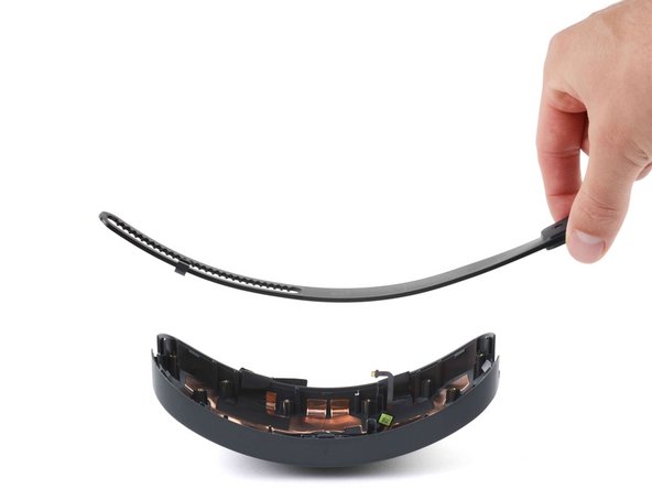
- Use a T5 Torx screwdriver to remove the four 4.1 mm-long screws securing the headstrap guide.
- Remove the headstrap guide
- The headstraps will spring up when the guide is removed.
- Remove the left and right headstraps
- During reassembly, reinstall the right headstrap first and the left one on top of it.