Mac Studio 2023 Antenna 2 Replacement
ID: 165078
Description: Use this guide to replace the right antenna...
Steps:
- Completely shut down your Mac Studio.
- Unplug all cables from your device.
- Flip your Mac Studio over and lay it down so the bottom faces up and the SD card slot and two front USB‑C ports are facing you.
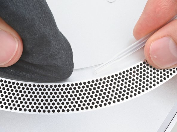
- Adhesive strips secure the bottom cover screw pad.
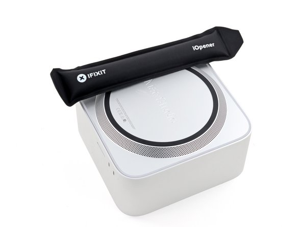
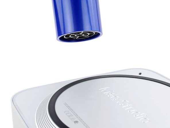
- Heat an iOpener and lay it over one of the bottom cover screws for two minutes to soften the adhesive near the screw—this is where you'll insert a spudger in the next step.
- You can also use a hair dryer or heat gun, but be careful as extreme heat will warp the pad.
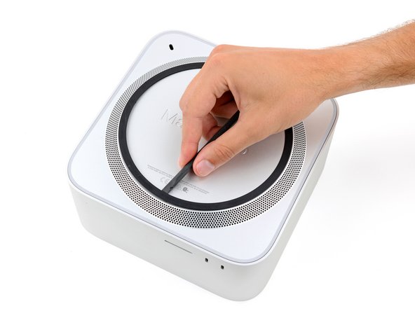
- Insert the point of a spudger under the pad's inner edge, near the screw you applied heat to in the previous step.
- This may take some force. If you're having trouble, apply more heat and try again.
- Use the spudger to lift the pad and separate the adhesive.
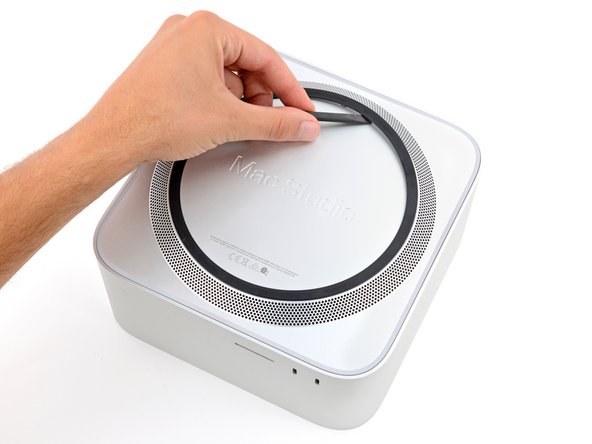
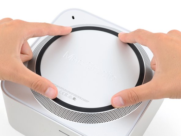
- Insert the flat end of a spudger under the pad.
- Slide the spudger under the entire pad to separate the remaining adhesive.
- Remove the bottom cover screw pad.
- During reassembly:
- If the adhesive strips are still sticky, you can reuse them.
- If you're applying new adhesive:
- Use the flat end of a spudger and your fingers to scrape up and remove the old adhesive strips.
- Use isopropyl alcohol and a microfiber cloth to remove the old adhesive residue.
- If you don't have replacement adhesive, you can use strips of thin, double-sided tape 2–3 mm wide.
- Apply the new adhesive strips to the bottom cover and remove their liners.
- Firmly press the bottom cover screw pad into its recess to secure it.
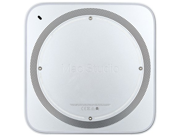
- While the Mac Studio uses Torx Plus screws, standard Torx bits work. Make sure to apply constant, downward force to prevent stripping.
- Use a T10 Torx screwdriver to remove the four 8 mm‑long screws securing the bottom cover.
- Throughout this repair, keep track of each screw and make sure it goes back exactly where it came.
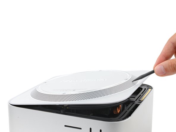
- Insert the point of a spudger in one of the bottom cover's ventilation holes and lift the cover until you can grab it with your fingers.
- Remove the bottom cover.
- To orient the bottom cover, align the Kensington lock cutout in the top left corner with the corresponding one on the internal frame.
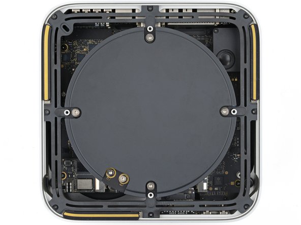
- Use a T10 Torx screwdriver to remove the six screws securing the power supply:
- Four 6 mm‑long screws
- Two 7 mm‑long screws with washers
- You may need to remove a sticker to access these screws. If you do, save it for reassembly.
- Flip your Mac Studio around so the rear ports are facing you.
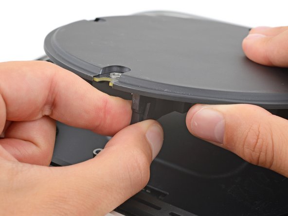
- A tight plastic latch secures the power cord port cable.
- Firmly hold the power supply with one hand and lift up the edge near the power cord port.
- With your free hand, pinch the head of the power cord port connector to unclip it and pull straight down to disconnect the cable.
- Only grab the power supply by its edges. Various power components and capacitors are left exposed.
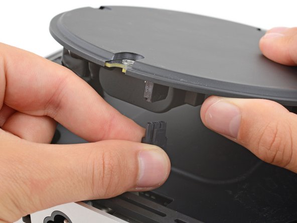
- Carefully tilt the power supply away from the power cord port so it's at a 90-degree angle.
- Be careful not to strain the cable that's still connected to the power supply.
- Keep the power supply tilted up for the next step.
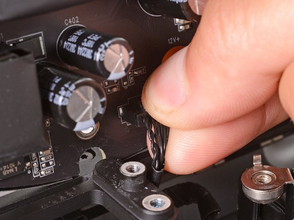
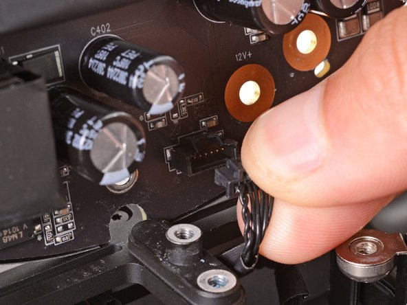
- A delicate plastic clip secures the power supply signal cable.
- With your free hand, pinch the head of the power supply connector to unclip it and pull straight away from the socket to disconnect the cable.
- Remove the power supply.
- Flip your Mac Studio around so the SD card reader and two front USB‑C ports are facing you.
- Use a T6 Torx screwdriver to remove the eight screws securing the internal frame:
- Seven 5 mm‑long screws
- One 4 mm‑long screw
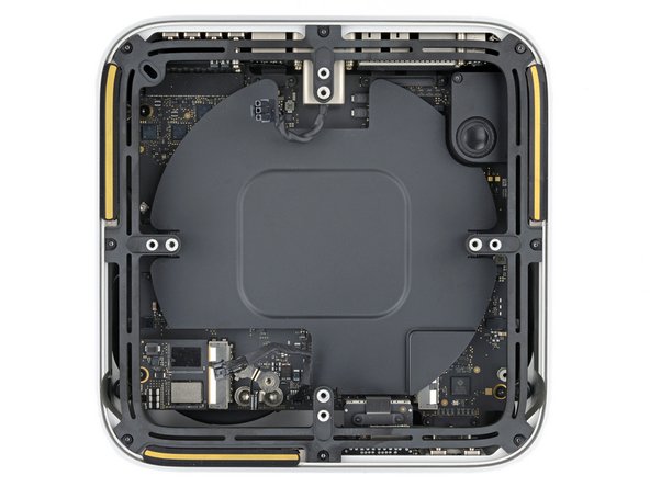
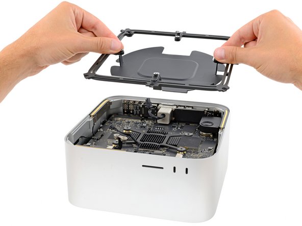
- Slowly lift the internal frame straight up and remove it, making sure no cables get snagged.
- During reassembly, make sure the power supply signal cable and power cord port cable don't get stuck under the frame when lowering it into place.
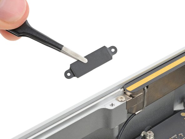
- Use a T3 Torx screwdriver to remove the two 2 mm‑long screws securing the antenna cable cover.
- Use tweezers or your fingers to remove the cover.
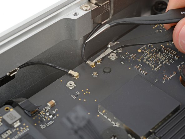
- Insert one arm of a pair of angled tweezers under the metal neck of antenna 2's coaxial connector and lift straight up to disconnect it.
- To reconnect the cable, hold the connector in place over its socket and press down with the flat end of a spudger—the connector should snap into place. If you're having trouble, don't try to force the connector over the socket. Reposition it and try again.
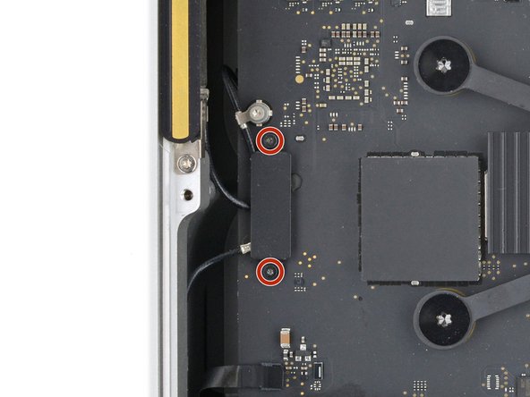
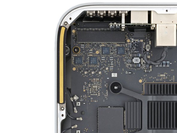
- Use a T5 Torx screwdriver to remove the two 3.5 mm‑long screws securing antenna 2.
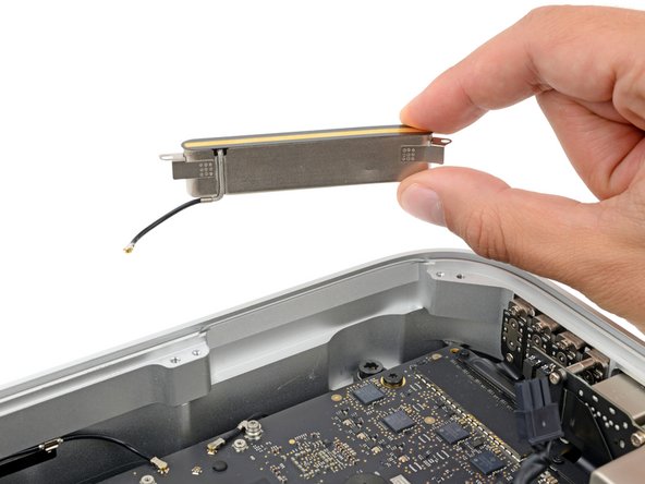
- Remove antenna 2.