HP EliteBook 840 Aero G8 Motherboard Replacement
ID: 168067
Description: This guide will demonstrate the replacement of...
Steps:
- Turn the laptop upside-down.
- Remove all five of the 4.48mm housing screws using a Philips #0 screwdriver.
- Remove the cover using an iFixit opening tool.
- Using the iFixit opening tool, remove the right-hand side speaker.
- Using the iFixit opening tool, remove the left-hand side speaker.
- Using the plastic spudger, disconnect the speaker power cable.
- Remove the wire from the device apparatus until it is fully isolated. The speaker system can now be removed from the computer to fix or replace as needed.
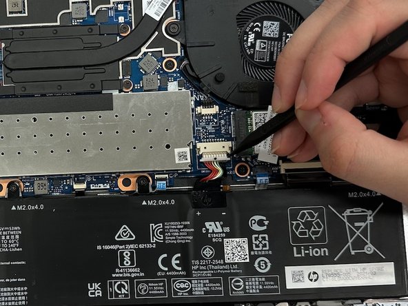
- Using the spudger, unplug the battery from the motherboard.
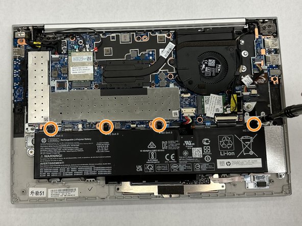
- Use the PH1 screwdriver to remove the screws from the battery.
- Set aside the four 4.48mm screws.
- Remove the battery from the casing.
- Using the spudger, gently unplug the RTC battery from the motherboard.
- Using the spudger, unplug the fan power cable from the motherboard.
- Use the PH1 screwdriver to remove the three 4.48 mm screws.
- Remove the fan from the computer.
- Use the PH1 screwdriver to unscrew the heat sink from the motherboard.
- Set aside the four 4.48mm screws.
- Remove the heat sink from the computer.
- Use ESD-safe tweezers to disconnect the display cables from the WAN module.
- Using a spudger, disconnect the display power cable from the motherboard.
- Use a PH1 screwdriver to remove the 4.48 mm screw that secures the WAN card on the left side of the motherboard.
- Use a PH1 screwdriver to remove the 4.48 mm screw that secures the WLAN card located on the right side of the motherboard.
- Using the iFixit opening tool, disconnect the camera power cable on the left hand side of the motherboard.
- Using the iFixit opening tool, disconnect the camera connection cable from the right-hand side of the motherboard.
- Using a PH1 screwdriver, remove the bracket holding the left side of the motherboard in place. These four screws are the longer of the two types of screws found in this laptop, measuring 4.48mm in length.
- Using the iFixit opening tool, unplug the USB board from the motherboard.
- Using the iFixit opening tool, unplug the fingerprint reader from the motherboard.
- Using the iFixit opening tool, unplug the NFC module from the motherboard.
- Using the iFixit opening tool, disconnect the click button assembly from the motherboard.
- Using the iFixit opening tool, disconnect the touchpad from the motherboard.
- Using tweezers, gently pull on the smart card reader board to disconnect it from the motherboard.
- Using the iFixit opening tool, disconnect the motherboard's power cable.
- Use the PH1 screwdriver to remove the two 4.48mm screws from the motherboard.
- Use the PH1 screwdriver to remove the three 2.52mm screws from the motherboard.
- You can now remove the motherboard from the computer to replace or fix it, as needed.