Shark IC160 ICZ160 P50 Floor Nozzle Teardown
ID: 169779
Description: My Floor Nozzle stopped working suddenly,...
Steps:
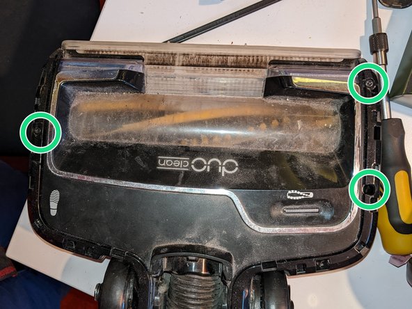
- Remove soft brush roll and bottom cover as shown in manual
- remove all long TX15 screws, shown in red
- remove 3 smaller TX10 screws in blue
- Once the screws have been removed, the wheels can be pulled out slightly, this is nececcary to remove the top trim.
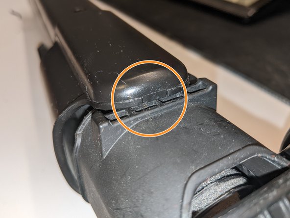
- Starting from the hinge side, pry the trim pieces up with a plastic spudger.
- Work your way towards the front of the unit. The clips are fairly tough and require a good bit of force. If there is too much resistance double check that all screws are removed in step 1!
- Once the trim is removed, the 3 short TX15 screws can be undone.
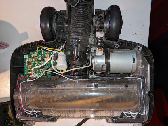
- the top lid should come off with very little resistance. Now the inside can finally be accessed!
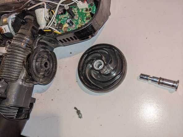
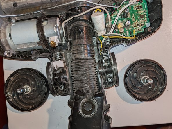
- To remove the wheels, carefully pry out the metal axles. Be sure all the scews in step 1 have been removed, as these hold the axles in place.
- The wheels are asymmetrical, not the side each goes to. There is a small imprint L or R on mine.
- Replacing the LEDs, Brush Motor, and Brush roll is possible with further dissasembly. There is also a microswitch to detect if the unit is snapped upright that shuts of the brushes. This can also be easily replaced once torn down this far.
- The back of the Hoseguide has 2 TX10 screws that need to be removed.
- The cover can the be unclipped starting from the tab at the bottom.
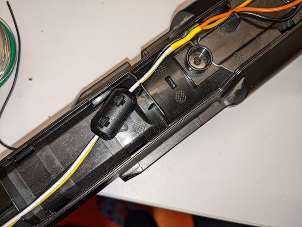
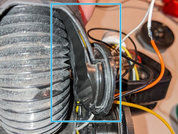
- note the location of the ferrule around the white, yellow and black wire. It had to be all the way at the bottom for my cover to go back on.
- I cut the wires below the ferrule and soldered new wires to the section going thru the hinge, your unit should have black white and yellow running all the way thru to the head.
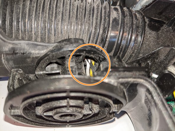
- Note the break in the wire. Wires used are 20AWG. Unfortunately Shark used standard PVC wires not suitable to constant bending loads. I recommend replacing with highly flexible signalling or probe wire with very fine strands to prolong the life of the repair.
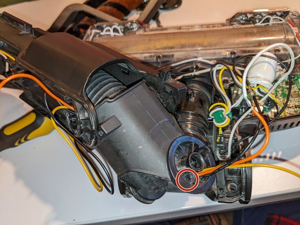
- There is a screw (red) holding the cable channel cover in place, remove this to carefully extract the cable channel (blue). This will make replacing the wires much easier! I only found out after carefully pulling the new wires thru soldered to the old...