SUV Defenders Teardown
ID: 171030
Description: Complete teardown guide of Kmart SUV Defenders...
Steps:
- BATTERY OVERVIEW
- RC Car Transmitter holds 2x AA batteries remove prior to teardown. Battery casing fastened by one M2x4 silver screw.
- RC Car Body holds 4x AA batteries and was also removed prior to the product teardown. Battery casing fastened by one M2x4 silver screw.
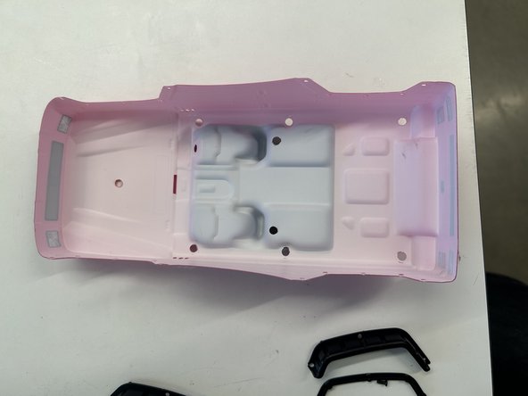
- CAR BODY & TOP TEARDOWN
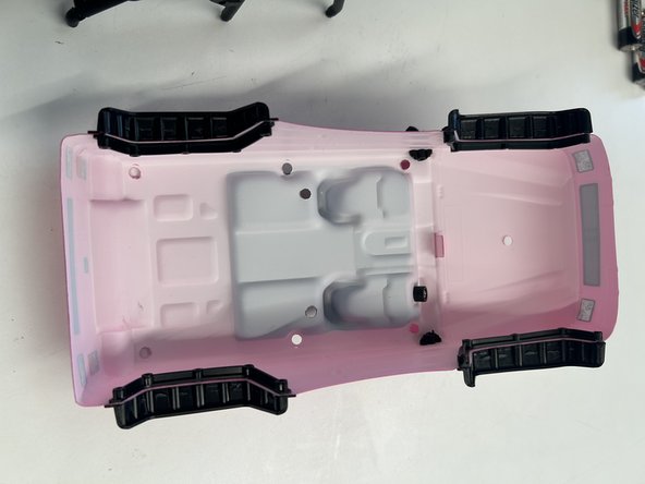
- To remove the polyethylene terephthalate (PET) plastic body of the car was only held together by three black clips, 2 located within the cage section and 1 located on the hood of the car. Simply removed by pulling them out.
- The roof of the cage was held in by 6 black anodised M2x4 screws located on the sides of the cage. Removed with Stanley swivel-head screwdriver.
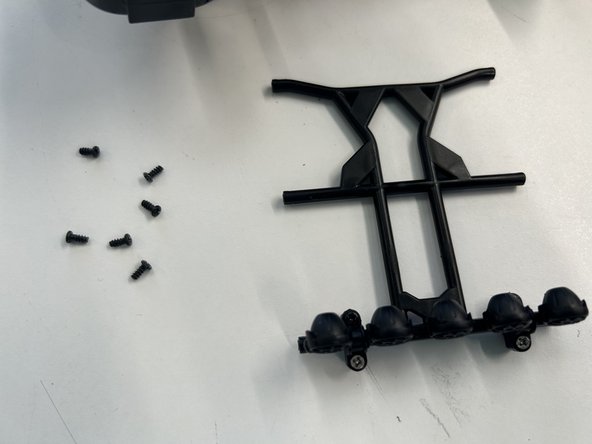
- FLOOD LIGHTS TEARDOWN
- Previously shown cage roof with 6 black screws.
- The flood lights were fastened with 4 black clamps pieces that had two silver M2x4 screws and two black anodised M2x4 screws. Removed with Stanley swivel-head screwdriver.
- CAGE TEARDOWN FROM CAGE BODY
- Sides of the plastic cage were fastened from underneath the body of the car, with six M2x4 silver screws inside of black plastic spacers.
- Extra wheel on back was only fastened using one silver M2x4 screw. All removed with Stanley swivel-head screwdriver.
- FULL CAGE TEARDOWN
- Wheel holder was fastened with two silver M2x4 screws on the back of the cage. Removed with Stanley swivel-head screwdriver.
- Sides and middle cage separated with only two black anodised M2x4 screws. Removing one from each side easily split apart the cage
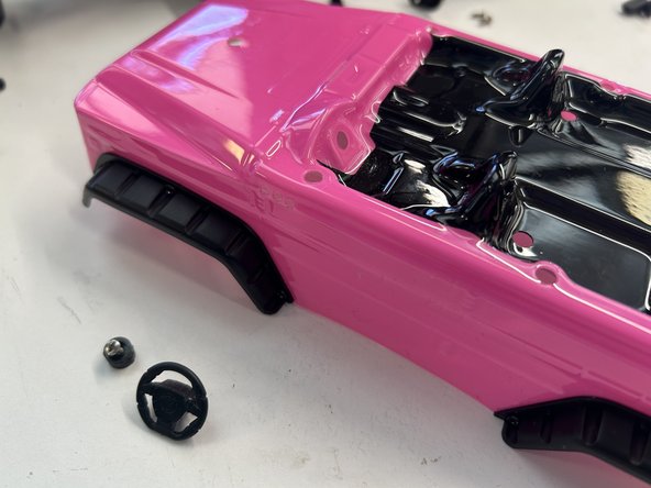
- WINDSCREEN & STEERING WHEEL TEARDOWN
- Main windscreen plastic part was easily removed by pulling it out once cage roof is fully removed.
- Headlights removed from clamps that were fastened with 1 black anodised M2x4 screw on each side. Once the screw was removed I was able to twist the clamp and separate the headlights from the windscreen.
- Wheel teardown had one M2x4 screw in a plastic black spacer. All were removed with a Stanley swivel-head screwdriver.
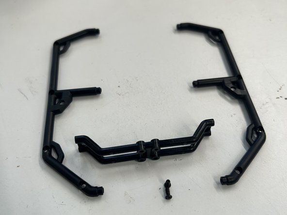
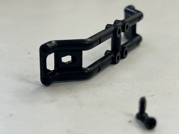
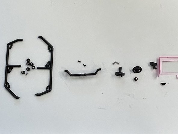
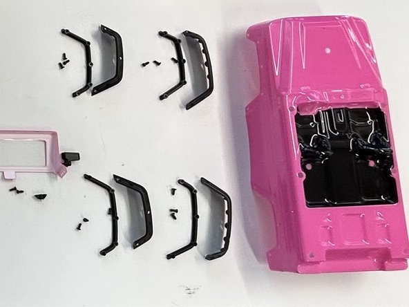
- FRONT & REAR FENDERS TEARDOWN
- Front and rear fenders each had 3 black anodised M2x4 screws removed with Stanley swivel-head screwdriver. Once removed there was also a backing inside the car body that also was torn down and removed with each fender.
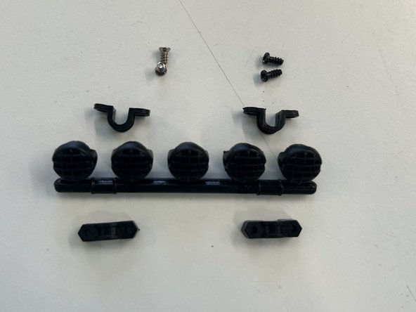
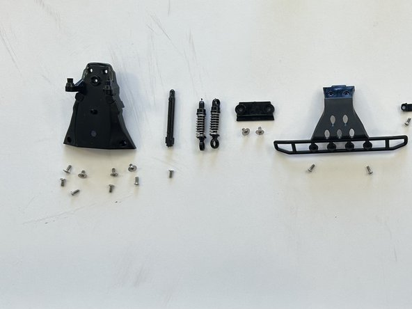
- Exploded view of what the components should look like afterwards.
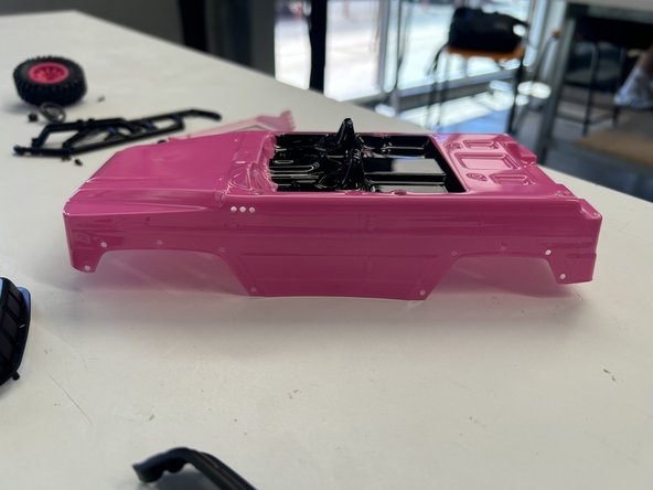
- MIDDLE & FRONT PROTECTOR TEARDOWN
- Removing the middle protector, made from acrylonitrile butadiene styrene (ABS) had four M2x4 silver screws protecting the main circuit board. The protector and had two black (ABS) beams that the clips for the pink plastic body would clip into.
- The front protector (ABS) had 8 silver M2x4 screws protecting the front wheel's motor. Four screws had washers on that fastened the front of the car, while the other four screws were on top of the protector fastened into the body.
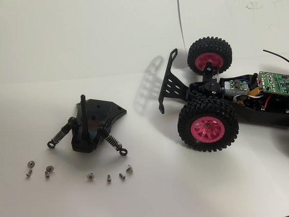
- FRONT PROTECTOR DISASSEMBLY
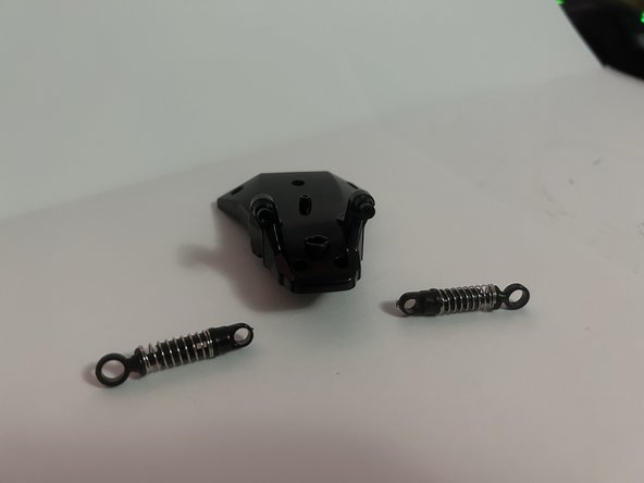
- Black (ABS) beam that was used to clip together the pink body of the car to the internals was fastened by one silver M2x4 screw.
- Front shock springs removed by just pulling them apart as they were friction fitted. Both came off quiet effortlessly without risk of harm.
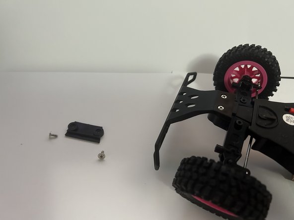
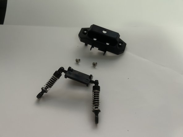
- Front plate that held bumper and stabilisers in place was fastened into RC car internals with two silver M2x4 screws. All were removed with a Stanley swivel-head screwdriver.
- BUMPER TEARDOWN
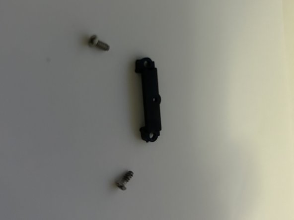
- After plate was removed from bumper, two additional M2x4 silver screws were unscrewed to removed bumper from car.
- Another clamp had to be removed to also remove the spur gear that control the front wheel's turning function. Only had two silver M2x4 screws to remove.
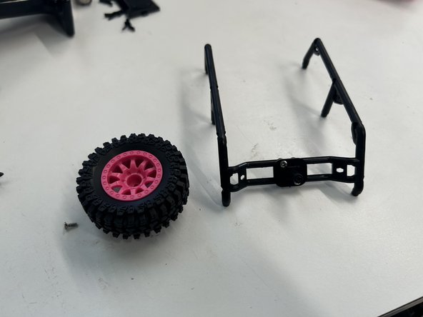
- FRONT WHEEL TEARDOWN
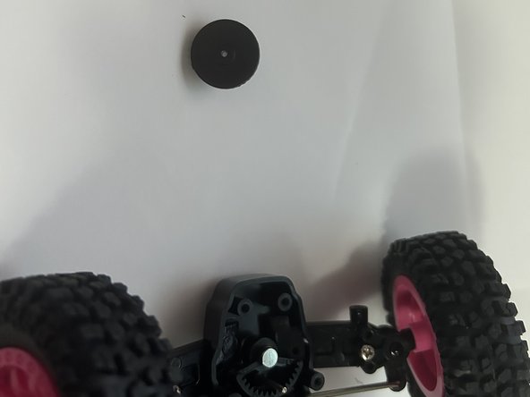
- Front wheels fastened by one Stainless steel M2x4 screw each. Both were removed with a Stanley swivel-head screwdriver.
- Both front stabilisers were fastened with one Stainless steel M2x4 screw each and the stabiliser's metal bar could be twisted out of the stabiliser plate.
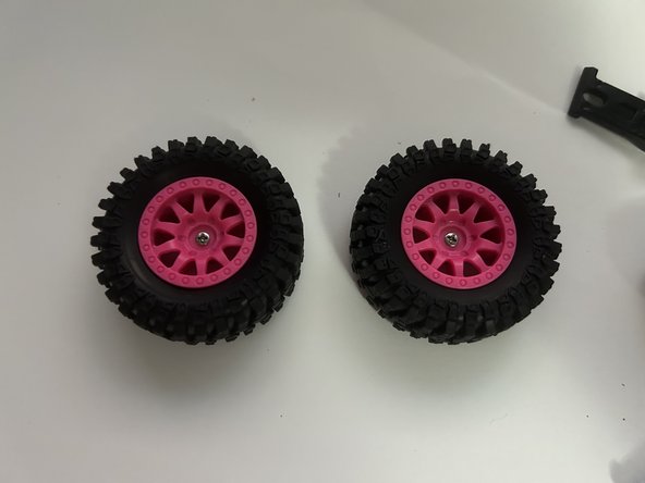
- REAR WHEEL TEARDOWN
- Front wheels only screwed in with Stainless steel M2x4 screw. Connected into the side pole that goes across the whole front of the car.
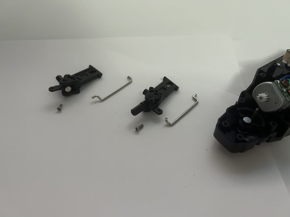
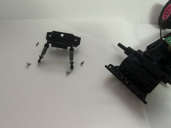
- Rear shock springs and rear protector casing fastened by 4 Stainless steel M2x4 screws. Two of the screws that held the bottom of the shock springs also has washers attached.
- To remove the shock springs from the rear casing there are only 2 M2x4 Stainless steel with Stainless steel washers fastened to be removed.
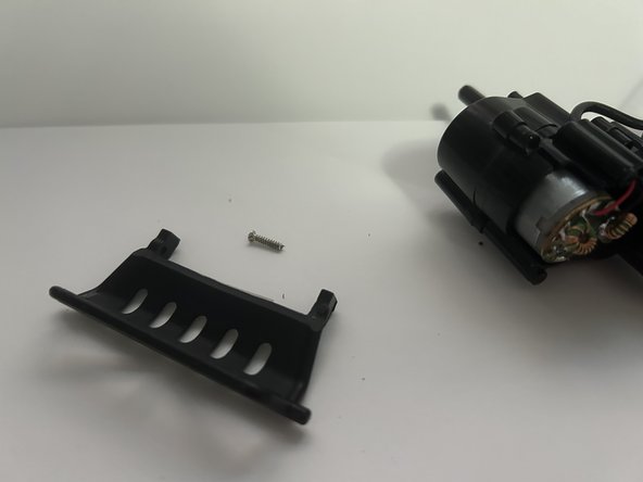
- REAR MOTOR FRONT TEARDOWN
- To expose the rear motor the (ABS) rear motor casing had one M2x6 and one M2x4 Stainless steel. The M2x6 was on the outer side for a more secure fasten.
- Rear bumper had the other M2x6 fastening it in its place. All were removed with a Stanley swivel-head screwdriver.
- REAR MOTOR BACK TEARDOWN
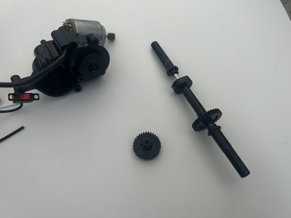
- The rear motor back casing was held by an additional 3 M2x4 Stainless steel screws to hold both the rear wheel's pole and the rear motor.
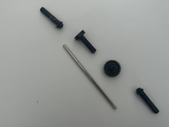
- After all prior screws are removed the pole for the rear wheels should detach from the rear motor which are all loosely fitted to allow for the spur gears to rotate the rear wheels.
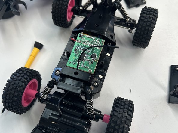
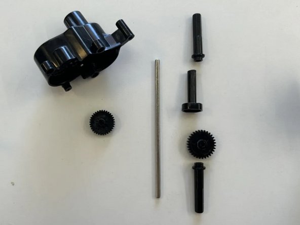
- INTERNALS TEARDOWN
- On/ Off switch was fastened into a fixed position with two M2x2 screws. The switch was connected with two wires to the main circuit board.
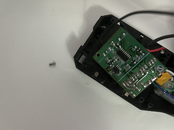
- Circuit board can be removed from fixed place, as it is only fastened by one M2x4 screw.
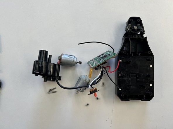
- After removing all screws all electrical components (front/rear motors, switch and circuit board) should all be loose from the internals body. All are connected and could be separated if wires were to be cut/removed.
- Exploded view of what the components should look like afterwards.
- Exploded view of what the components should look like afterwards.
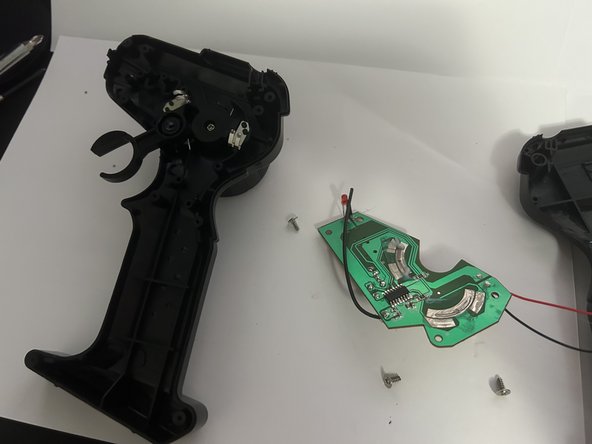
- RC TRANSMITTER TRIGGER TEARDOWN
- Two half bodies of the transmitter fastened together with 4 Stainless steelM2x4 screws remove with Stanley swivel head screwdriver.
- Transmitter circuit board fastened with 3 M2x4 screws also have washers on each remove with Stanley swivel head screwdriver.
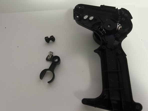
- Trigger should easily be removed by pulling it out be careful of metal component of trigger could cause minor harm. The additional side buttons (there for aesthetic purposes) should also be able to be removed from the transmitter body.
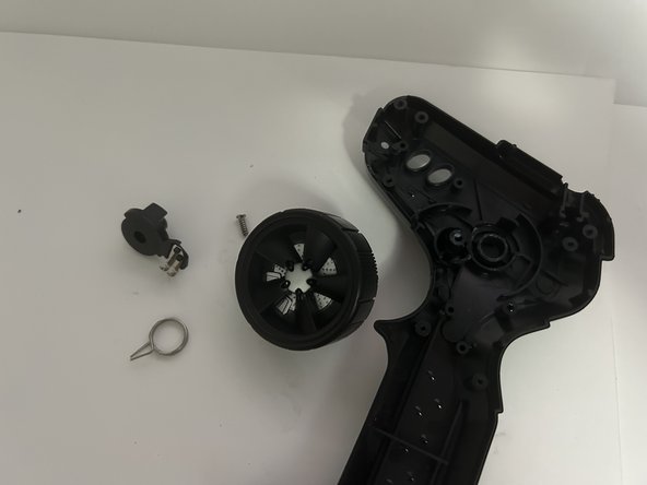
- STEERING TEARDOWN
- Spring located within the trigger also can fall out when removing trigger be mindful of it's location behind the trigger. Be mindful the spring behind the trigger is smaller than the steering wheel's if reassembling.
- Located on the other side of the transmitter body is another clamp to hold together the trigger to avoid loose fitting. Fastened with one M2x4 Stainless steel screw with a washer only component to remove from this body.
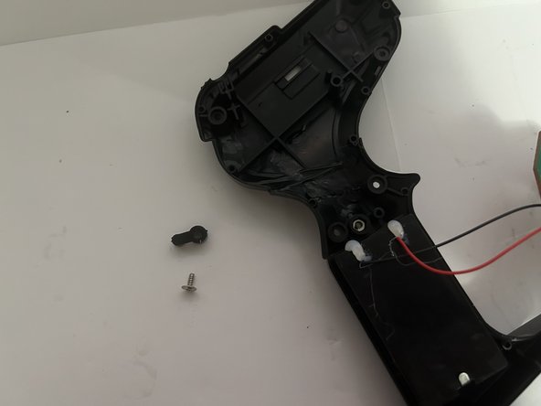
- Steering wheel held together with one M2x4 Stainless steel screw when removed all three parts should separate. Be careful due to each part having been pre-lubricated and can slip from hands, particularly the spur gear and larger spring.
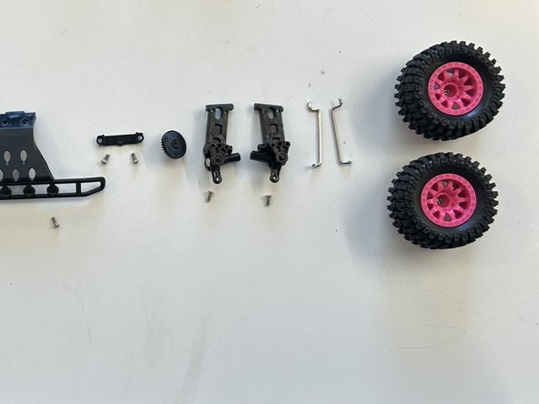
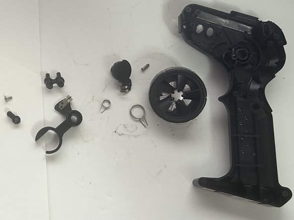
- Exploded view of what the components should look like afterwards.