Acer Spin 3 SP315-51-757C Screen Replacement
ID: 171105
Description:
Steps:
- Remove eleven Phillips #0 screws from the back panel.
- Using an opening tool, pry open the back panel, starting at the silver screen hinges.
- You may need to apply more force than usual. If you don't find any success at the hinges, you can try to start at another area that looks easier to open.
- You can also use some plastic opening picks to help hold parts of the panel open while you work on other sides.
- Lift the back panel off of the laptop.
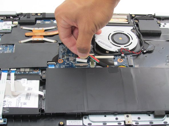
- Remove the two Phillips #0 screws holding the battery inside the laptop case.
- Using either your hands or a pair of tweezers, carefully pull the battery's cable out of its motherboard port.
- Using your hands, lift up on the battery from its slot, and carefully slide it away from you before fully lifting it out of the case.
- The charger port's inner cable may be covered by a manufacturer sticker, which can be easily removed.
- Using your nails or tweezers, unplug the charger port cable from the motherboard.
- Gently lift the charger port out of its slot in the laptop casing.
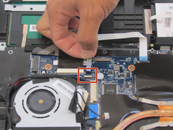
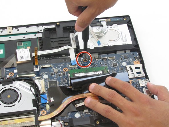
- Lift the three black tabs to release the cable connectors.
- After the tabs are lifted, the white cables with blue ends can be pulled out of their slots.
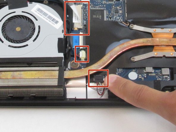
- Remove the cables near the fan by pulling them carefully out of their slots.
- Remove the single Phillips #0 screw.
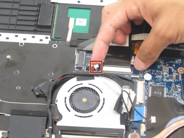
- Unplug the speaker cable.
- Unplug the secondary speaker cable.
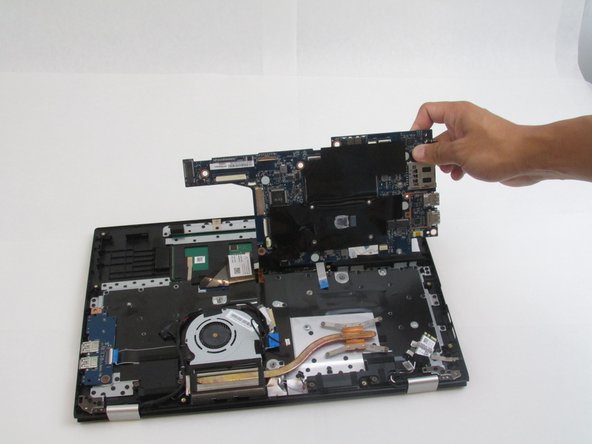
- Remove the three Phillips #0 screws attached to the motherboard.
- Use a Phillips #0 screwdriver to remove four screws from the heat sink.
- Carefully slide the motherboard from under the heat sink (it is easiest to slide the motherboard to the right).
- Remove the screws from the "L" and "R" plastic pieces using a Phillips #0 screwdriver.
- Remove four screws from the metal hinges in the corners using a Phillips #0 screwdriver.
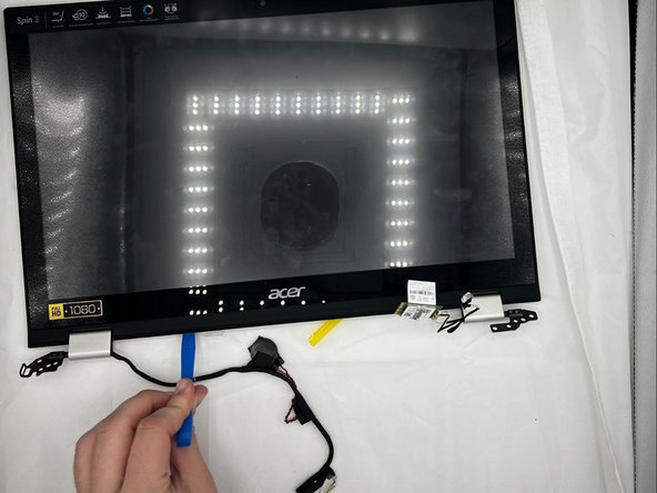
- Using an opening tool, separate the bezel from the rest of the device.
- Remove the Phillips #0 screws attaching the screen to the display assembly.
- Using your hands, remove the screen.