HMD Skyline Charging Board Replacement
ID: 173719
Description: Follow this guide to replace the charging board...
Steps:
- Let your phone's battery drain below 25% before starting this repair. A charged lithium‑ion battery may catch fire if damaged.
- Unplug all cables and completely power off your phone.
- Firmly press a SIM eject tool, bit, or straightened paper clip into the SIM tray hole on the bottom edge of your phone until the tray ejects.
- Remove the SIM card tray.
- A thin rubber gasket around the SIM tray provides water and dust protection. If this gasket is damaged or missing, replace the gasket or the entire SIM tray to protect your phone's internal components.
- A screw‑driven camshaft in the bottom left corner pushes the back cover away from the phone, creating a gap to begin separating the cover.
- With the back cover facing up, use a T3 Torx screwdriver to turn the screw in the bottom edge counterclockwise until the back cover pops up.
- Before separating the back cover, note the following:
- There's a seam just under the back cover panel. Don't insert your tool here.
- Insert your tool completely under the back cover, so it's between the frame and the underside of the back cover.
- Insert an opening pick under the bottom left corner of the back cover and slide it along the bottom edge to release the clips and separate the adhesive.
- You should feel and hear the back cover clips release. If you don't, insert the pick deeper and try again.
- Continue sliding the pick under the perimeter of the back cover to fully separate the clips and adhesive.
- Lift and remove the back cover.
- During reassembly:
- Now is a good time to test your phone before sealing it up. Power it on and check that it works. Power it back down before you continue reassembly.
- If you're installing a new back cover:
- Make sure you remove all liners from the underside.
- Use the flat end of a spudger to press the small cable above the wireless charging coil into place over its alignment posts.
- Rotate the bottom screw clockwise to ensure a proper fit.
- Place the back cover onto the frame and firmly squeeze around the perimeter to reengage all the clips.
- Use a T3 Torx screwdriver to remove the two screws securing the battery connector cover.
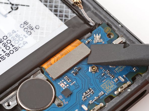
- Gently flip the graphite sheet on the battery over the top edge of your phone.
- Be careful not to tear the sheet, as it's very delicate.
- Insert the point of a spudger in the notch on the left edge of the battery connector cover and pry up to release its clips.
- Only insert your tool enough to pry up the cover. Otherwise, you may accidentally disconnect the rear camera press connector.
- Remove the cover.
- During reassembly, firmly press the cover into place to engage the clips.
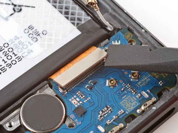
- Insert the tip of an opening pick under the top edge of the battery press connector and pry up to disconnect it.
- Check if the rear camera press connector got disconnected during the previous step. If it did, reconnect it.
- To reconnect a press connector, align it over the socket and gently press down on one side until it clicks into place, then press down on the other side. It might take a few tries to align the connector.
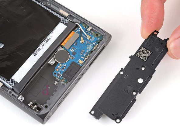
- Use a T3 Torx screwdriver to remove the seven screws securing the loudspeaker:
- Four 3.9 mm‑long screws
- Three 4.9 mm‑long screws
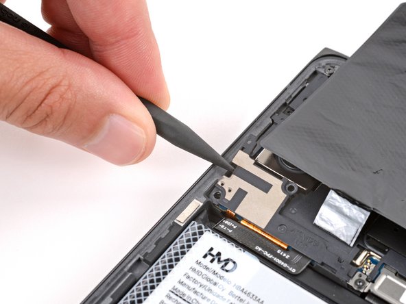
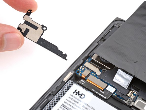
- Insert the tip of a spudger under the center of the loudspeaker's top edge and lift to release its clips.
- Don't pry against the battery, and be very careful not to puncture it with your tool.
- Remove the loudspeaker.
- During reassembly, lay the loudspeaker in place and press firmly around its perimeter to engage the clips.
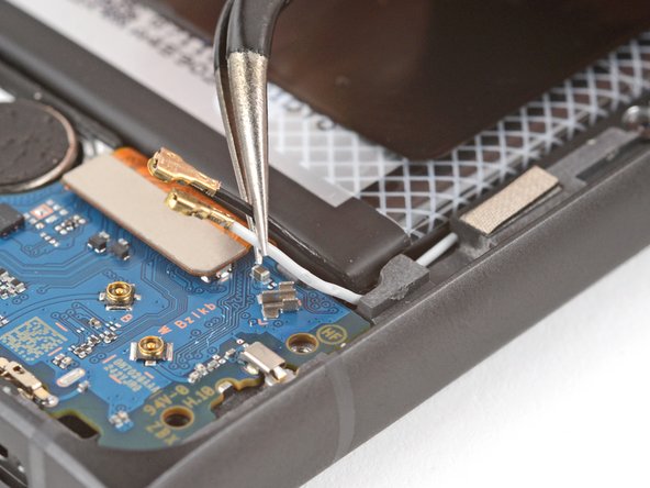
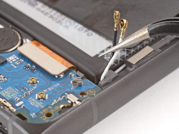
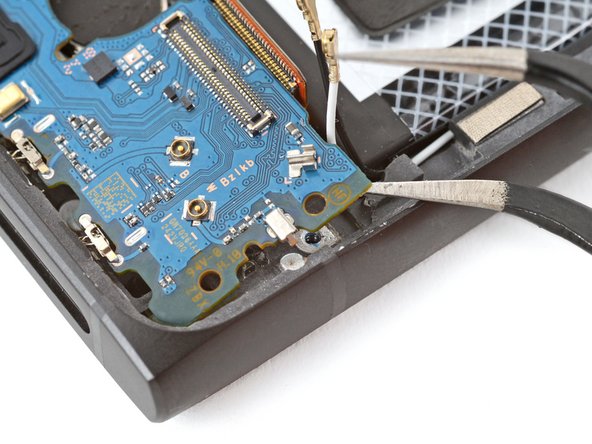
- Slide an arm of a pair of angled tweezers under the metal neck of one of the antenna connectors on the charging board and lift straight up to disconnect it.
- Make sure the tweezer arm is as close to the head of the connector as possible.
- Repeat the process to disconnect the other coaxial connector.
- During reassembly:
- Use the markings on the board to make sure the cables get connected to the correct socket—B for black and W for white.
- Hold the metal neck of the antenna connector with a pair of tweezers and align the head over its socket on the board.
- Use the flat end of a spudger to press straight down on the connector head—it should snap into place. If you're having trouble, reposition the head and try again. Don't try to force the connector into place, or you risk damaging the charging board.
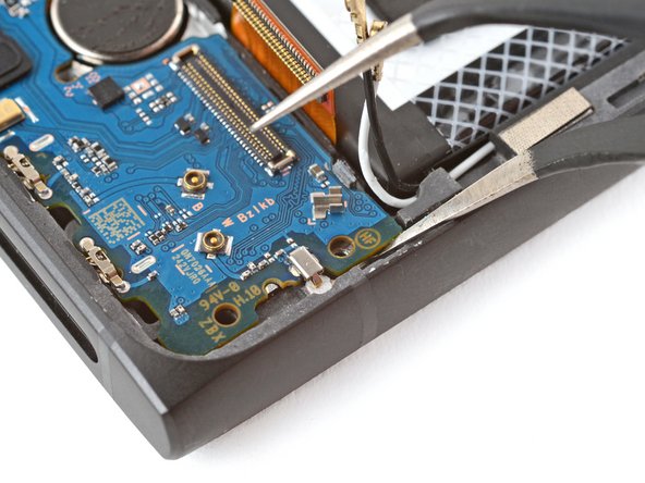
- Use tweezers or your fingers to carefully grip both antenna cables and gently lift them out of their metal clips on the board.
- Be very careful not to scrape up or damage any of the small, surface-mounted components around the connector during this step.
- Insert the flat end of a spudger under the bottom right corner of the charging board press connector and pry up to disconnect it.
- Be very careful not to puncture the battery during this step.
- Before unclipping the charging board, double-check that you removed the SIM card tray.
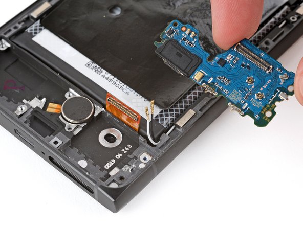
- Slide an arm of a pair of angled tweezers under the top right corner of the charging board and pry up to release the clip on the top edge.
- Lift the top edge of the board and remove it.
- During reassembly:
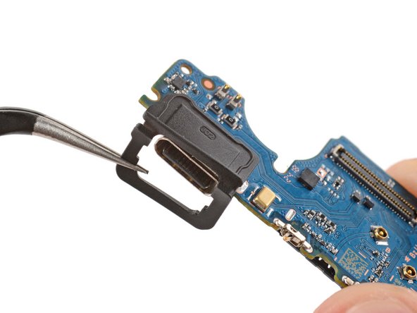
- Make sure your USB‑C port has a rubber gasket around it. If it doesn't, transfer the gasket from your old board, making sure the side with a cutout goes on the bottom.
- Insert the board at a downward angle so the USB‑C port goes into its cutout.
- Make sure none of the cables on the top edge get stuck under the board.
- Press down on the top edge of the board to engage its clip.