Zeiss Ikon Movielux Compact Projector Teardown
ID: 175753
Description:
Steps:
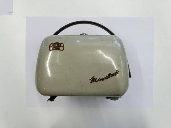
- A Zeiss Ikon 8mm Movielux projector from the late 1950's, this was built in Germany for the intention of family home cinemas, easy to set-up with it's portable design. Weighing 4.5kg, this device is sturdily built with quality materials, incorporating many smart and user centered, functional features.
- Length: 238mm
- Width: 124mm
- Height: 175mm
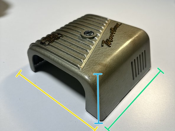
- Prying off the case shell (302g), it has the 'Zeiss Ikon' and 'Movielux' embossed in brass, attached using metal wires that hook into tiny slotted holes in the case.
- The mild steel case clicked onto the main frame snugly, with little grooves that slotted into the film arm holder. Suction keeps the shell on tight as it is a snug fit, there is no rubber gasket or lining.
- Finger hole on the bottom for ease of access when opening.
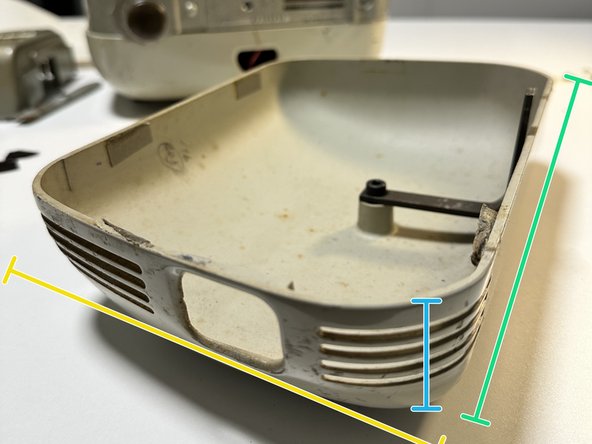
- Case is stamped and made out of mild steel, hand painted on the inside, power-coated on the exterior.
- Length: 233mm
- Width: 45mm
- Height: 154mm
- All dimensions throughout teardown are labelled as the projector in standing position (i.e. this case is laid flat, but its original position is upright)
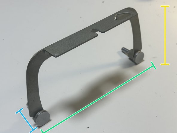
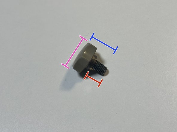
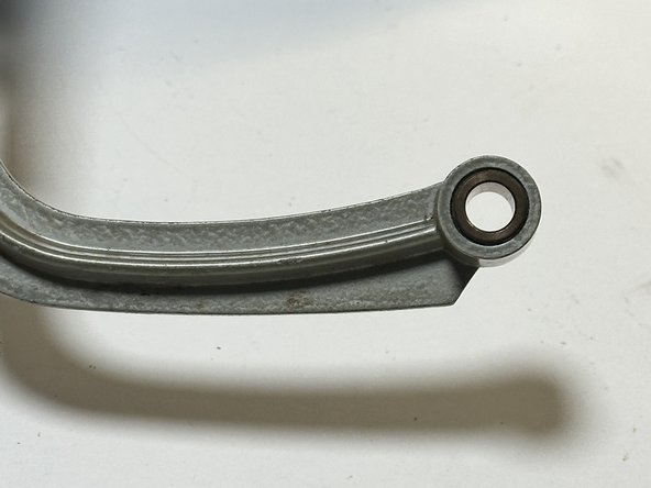
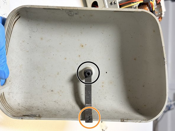
- Easily unfasten torx hand screw (8.5g) to access the U shaped arm which holds the film reels on the pivot pins.
- Pull the film reel arm (28g) out of its moulded position on the main mild steel frame, it may be a little stuck. Otherwise, it is relatively easy to remove with a bit of elbow grease.
- Length: 232mm
- Width: 43.0mm
- Height: 105mm
- Torx head diameter: 20.2mm
- Screw Length: 20mm
- Thread length: 9.6mm
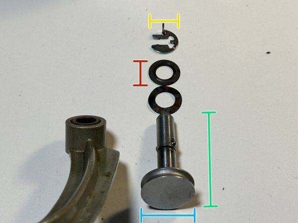
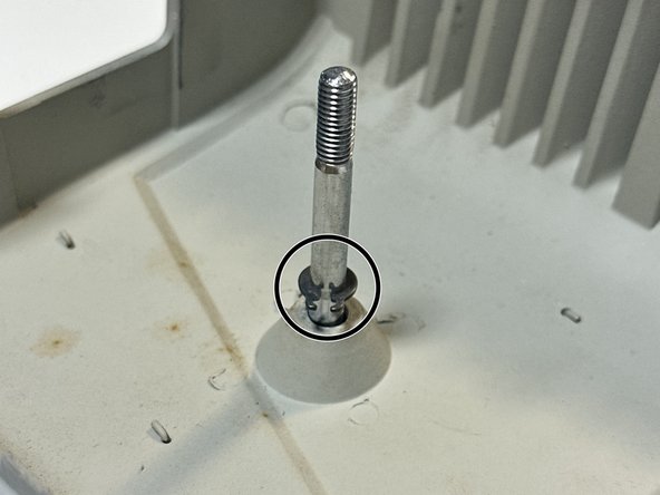
- Remove the pivot pin (27.3g) from the main projector arm, it pops out after removing the clasp washer using a pair of pliers, pushing it out. The film reels fit onto the long cylindrical section, one on each side of the arm.
- I noticed ball bearings that are very well imbedded into the shaft, and I suspect the pivot is made of two parts connected- head and shaft, however I was unsure how to further dissect and lacked the tools to do so.
- The pivot had two stainless steel washers as shown in the picture and a clasp washer which clicked on after the pivot passed through the film reel arm hole. The clasp stopped the pivot pin from sliding out of the hole.
- Length: 42.5mm
- Diameter: 22.0mm
- Clasp Diameter: 13.9mm
- Washer Diameter: 14.9mm
- Unfasten the big round head slotted screw using the appropriate screwdriver and easily lift off the case protecting the internals- circuits and wiring.
- The big round-head slotted screw fastening the internal case (181g) to the main frame is extremely difficult to remove from the case, as it has a snap lock washer which is extremely tight. Attempting using pliers to remove with no luck.
- Unable to get accurate bolt screw dimensions without removing from the case.
- Initially thought the main body frame is made out of an ABS like plastic, maybe bakelite but upon further inspection, it seems to be mild steel.
- Length: 114.5mm
- Width: 49.2mm
- Height: 118mm
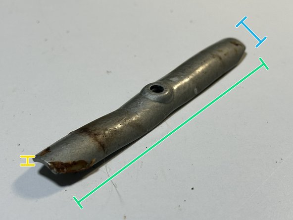
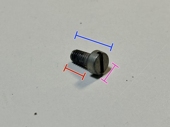
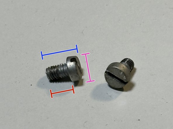
- Use a flat-headed screwdriver to remove the stainless steel, flat head, slotted screw (1.3g) joining the stand with the main frame, fast and simple.
- The stand is quite light (21g) but very rigid, acts as balancing stand for the projector to sit upright without teetering, especially important when in use watching films.
- Length: 103.5mm
- Width: 14.1mm
- Height/Thickness: 2.1mm
- Diameter: 6.7mm
- Screw Length: 11.1mm
- Thread Length: 8.0mm
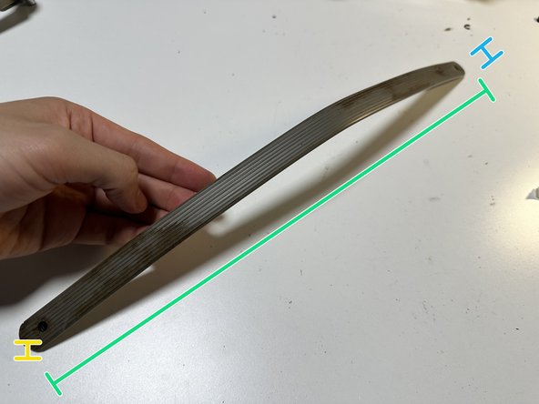
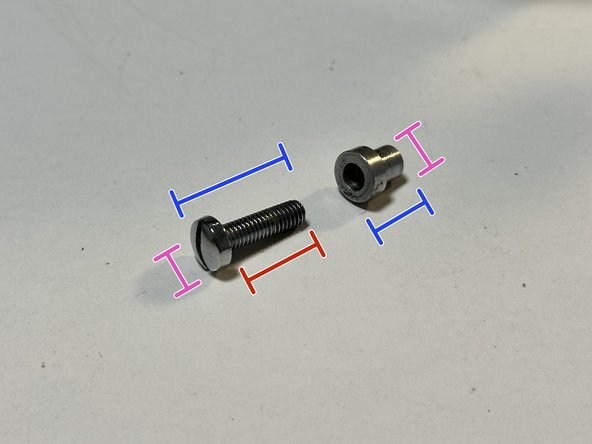
- Handle (42g) was unscrewed with a flat-head screwdriver, held by two stainless steel, slightly rounded head slotted screws (2g). The screw slotted into stainless steel holders (1.2g), which kept the screws snugly fitted in the cutout hole of the handle, which was made of a rigid yet flexible PP, nylon-like material.
- The handle fits the palm of the hand quite well, however elongated periods of time holding may hurt as the edges, though rounded, leave palm marks. Also, because of the projectors heavy weight the downwards pressure on your hands is quite severe.
- Length: 425mm
- Width: 19.5mm
- Height/Thickness: 4.5mm
- Head Diameter: 8.0mm, Holder Diameter: 8.2mm
- Screw Length: 17.7mm, Holder Length: 8.4mm
- Thread Length: 14.3mm
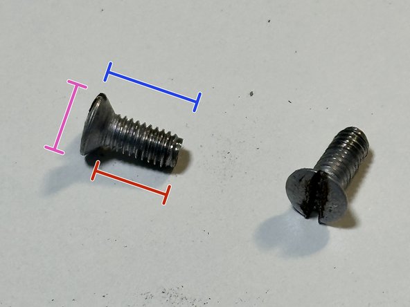
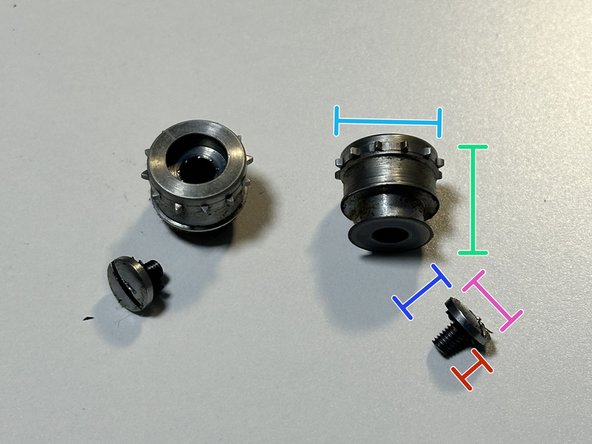
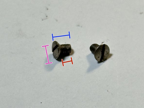
- Using a flat-head screwdriver, I easily removed the stainless steel, subtly rounded, countersunk screws (<1g) on the bottom of the projector, which kept the back case sealed.
- The tiny SS flat headed, slotted screws (<1g) in the spiky holders (8.9g) were extremely hard to remove, on my initial tries, it would deform and dent the screws. I tested using heavy force on twisting the screwdriver closer to the edges of the screw did the trick. Unsure what the function of the spikes were, maybe to do with the rotation?
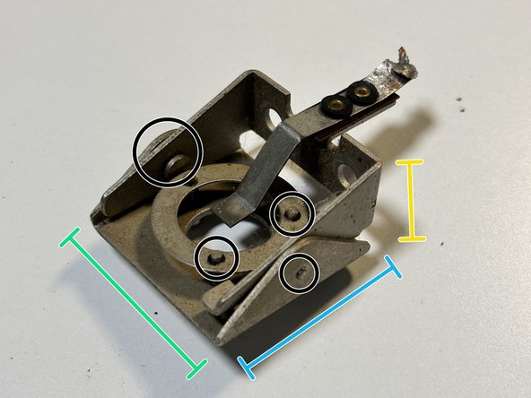
- I was unable to remove some of the screws, none of my slotted screwdrivers worked on them. An electric drill is definitely needed. I was confused how to remove the bottom right component, realised it's to adjust the angle of which the film is shone on the wall. (All components I was unable to remove are outlined in black throughout the guide)
- Length: 12.4mm
- Diameter/Width: 14.8mm
- Head Diameter: 5.5mm, Smaller Head Diameter: 7.4mm
- Screw Length: 10.5mm, Smaller Screw Length: 8.0mm
- Thread Length: 8.5mm, Smaller Thread Length: 6.7mm
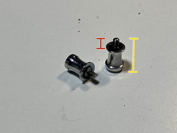
- Using a pair of pliers, I untwisted the tight kink in the knobs (4.3g), and then quickly unscrewed by hand. I did face moderate difficulty at first, just using my fingers to unscrew didn't budge the knobs and even using pliers they would slip against the shiny stainless steel knobs.
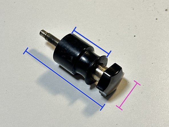
- I attempted removing the black knob with the hand screw head (24g), which I unscrewed counter-clock wise to the max by hand but it didn't come out so I used a pair of pliers to add additional force in twisting and eventually yanked it out. Nothing broke surprisingly, the ABS knob and shaft holder was very durable. It is a two piece component.
- However, I was unable to remove the far left round black knob, even yanking with all my strength with a pair of plier did nothing except crack and break off bits of the ABS plastic. All of these knobs and the spiky holder from previous step are used to guide the belt of film, like a conveyer belt of smooth knobs.
- Screw Length: 59.2mm, Holder Length: 26.2mm
- Diameter/Width: 20.4mm
- Height: 16mm
- Thread Length: 3.6mm
- The rough outline how the film roll moves from knob to knob.
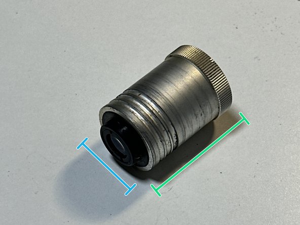
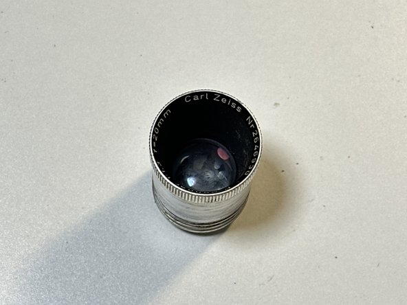
- I tried twisting and pulling on the projector lens (40.5g) by hand to remove it, and to my surprise it popped out quite easily with a twist and a tug.
- I assume film or translucent still images would've been placed behind this lens that focused the projection on a surface/screen, focusing it to make the projection clear and magnifying it.
- Length: 40.0mm
- Width/Diameter: 15.8mm
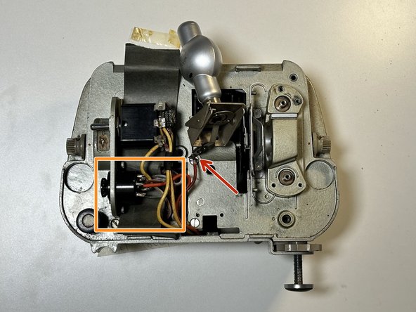
- The grey PP bulb is attached to the frame with 2 tiny slotted, flat head, stainless steel screws (<1g). Use a slotted head screwdriver to remove the screws.
- Grey bulb is still connected by a red wire soldered onto its frame. Twist it off using pliers.
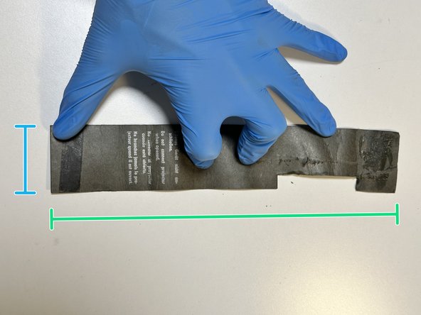
- Pulled the insulating piece of card like material (<1g) apart, glue and yellowed cellotape from the time degradation was already giving out. Reveals the inner workings of the on/off switch and the potentiometer wire hub connected to the copper wire.
- The newly revealed potentiometer knob and its wires is also screwed into the main frame with similar but slightly larger flat head slotted, stainless steel screws. Unsure how to detach wires soldered onto this component as of now.
- Length: 244mm
- Width: 44mm
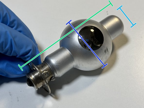
- This is the PP bulb and base (54.9g) after removing the red wire soldered on. It's shell houses a small, thin glass filament bulb which is the light source for the projector.
- The mild steel base piece (37.8g) twists and pops off easily from the bulb. This component allows the bulb to be connected to the rest of the circuit easily, through soldering and screwing it in.
- Unsure on how to further dissect the base piece, however I am certain is it multiple components riveted and screwed together. Some of the 'screws' have no slot, just completely smooth, and the few screws available were on so tight I was unable to remove with my thin slotted screwdriver.
- Bulb Length: 92.9mm, Base Length: 36mm
- Bulb Diameter: 42.6mm
- Bulb Width: 18.4mm, Base Width: 34mm
- Height: 20mm
- Remove the stainless steel, flat head, slotted screws (<1g) holding the potentiometer knob (23.1g) we saw in Step 10 using a flat-head screwdriver.
- Once screws are removed, the knob is easily pushed through the holes in the frame and pulled out of position. However, it is still connected to all the sets of wires soldered onto it.
- Using a pair of plier, I ripped the soldered wires off one by one. This was very difficult and required many attempts and tight clenching of the pliers, twisting and rotating them at various angles to weaken the bond, often ending up removing the small soldered platforms for each wire too.
- Length: 33.6mm
- Width: 26.8mm, Longest Width: 40.8mm
- Head Diameter: 5.3mm
- Screw Length: 8.0mm
- Thread Length: 6.1mm
- Flip projector over 180 degrees. Pry case, comes off relatively easily after removing base stand in Step 6 which held part of the case closed, as well as the external screws from Step 8.
- The slots for the stainless steel, subtly rounded, countersunk screws on the bottom of the projector we removed in Step 8.
- Length: 238mm
- Width: 124mm
- Height: 175mm
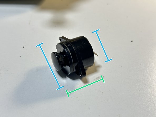
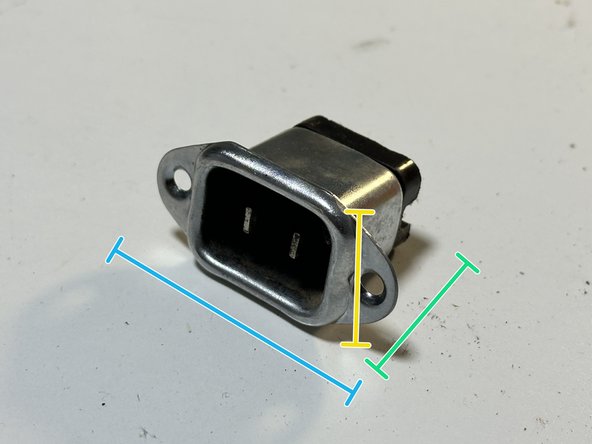
- Using a flat-head screwdriver, remove the small stainless steel, countersunk, slotted screws (1.1g), which joins the SS socket (22.2g) to the main frame. To power the projector, a specific cable is connect to the socket and into the wall. (The projector didn't come with the cable unfortunately.)
- Use pliers to remove the wires that are soldered onto the socket, they came off quite easily.
- Width: 43.2mm
- Height: 25.7mm
- Head Diameter: 5.1mm
- Screw Length: 9.8mm
- Thread Length: 5.3mm
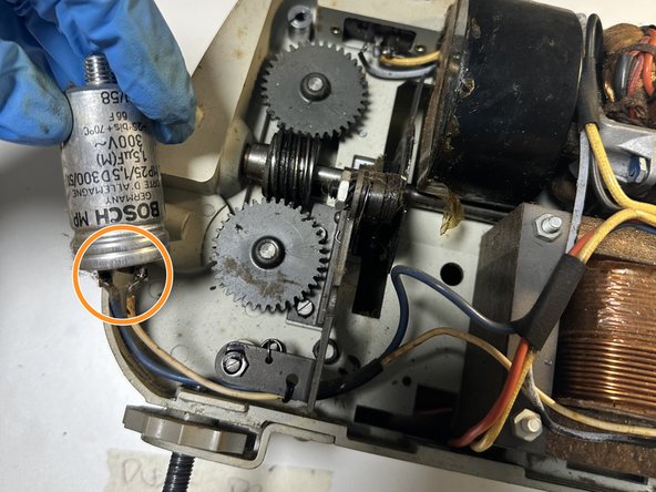
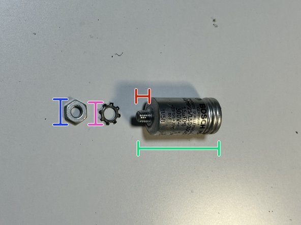
- Using a pair of pliers, unscrew the stainless steel nut (3.7g) on the end of the Bosch MP Capacitor (34.5g). It was a bit finicky and difficult to twist it out due to the poor range for hand movement in unscrewing it. The nut clamps onto the capacitor's thread and prevents any axial movement while keeping it fastened.
- After removing the nut and spikey washer and pulling the capacitor out, use the pliers again to rip off the yellow and blue wires soldered onto it. The spikey washer distributes the force evenly and its spikes clamp tight on the thread. The capacitor's job is to store and evenly distribute electricity throughout the projector's circuit.
- Length: 47.9mm
- Width/Diameter: 25.3mm
- Thread Length: 7.2mm
- Nut Diameter: 14.3mm
- Washer Diameter: 14.5mm
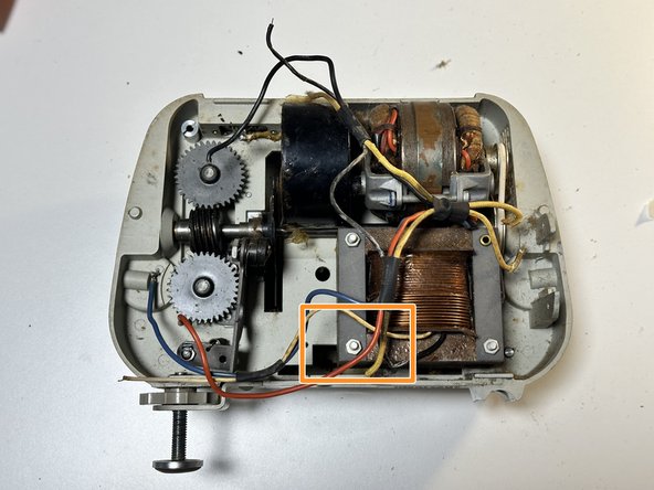
- By this point in the teardown process, I was running into issues scouring for more parts to take apart. Many of the components wouldn't budge when I tried yanking, pulling, rotating them with a pair of pliers. These included all the parts circled in black, the cogs, the coils and larger components. I tried all of them.
- It probably would've helped to have a wrench set as some of the screws were fastened with nut, which was why the screw wouldn't budge.
- The long bolt here was the only one that gave me a bit of budge after trying to loosen the nut on the left side, however it was too difficult trying to unfasten it; it was too small for my finger but the pliers were to large to rotate in that cramped area it sat.
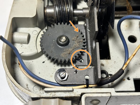
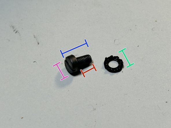
- That said, I did manage to remove the bottom stainless steel, flat-head, slotted screw (<1g) that fastened a section of a cog's frame. I attempted to remove the matching screw above it where the arrow points without much luck, as the cog blocks access to it- which makes me wonder how it was screwed in in the first place?
- Head Diameter: 5.3mm
- Screw Length: 7.3mm
- Thread Length: 5.8mm
- Washer Diameter: 12.3mm
- I was unsure how to remove the wires earlier in Step 10, but I've decided now to rip the wires loose from their soldered components using a pair of pliers. I tried removing them all, but when I pulled them out of one spot, they would be joined to another area, or even to the other side of the projector which was a huge problem without wire cutters.
- Some sets of wires are interconnected, such as the yellow one connects from the coil to the switch, so I had to flip the projector back and forth to see where connected where.
- I pulled off all the wires soldered onto the 'switch box', this took a bit of effort in twisting and yanking. I thought after that, the entire component would be easier to remove, however it was still solidly stuck in place.
- I used pliers to try crack open the 'switch box', hoping to discover any secrets to removing it, but all I got was some insight on how the flicking switch mechanism works, which was very interesting and well designed. It seems the switch was an on/off, but there was a third option, perhaps to switch the frame rate?
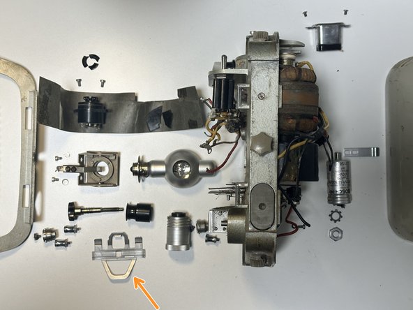
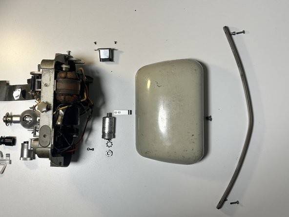
- This is an exploded view of all the parts I removed from the main body of the film projector. I was pondering how I would go about laying it out, due to the nature of the projector opening up on both sides.
- I chose to stand it up and have it in the middle, with components 'exploding' from both ends. However making it stand upright without falling was quite the challenge, because many of the parts were missing, not all of them, so the weight distribution became uneven- meaning one side (the back) still had more components untouched.
- This is also intriguing, it means the manufacturer had to have taken the weight of both sides into consideration too, in order to balance it- something I wouldn't have considered.
- There are a few components that I popped out after documenting the entire process and run out of picture space, so I have included them in the exploded view but won't appear in the teardown process (I have labelled some).
- It was difficult to format the exploded view into one image so I've split it into three more detailed pictures.