HMD Fusion Charging Board Replacement
ID: 176072
Description: Use this guide to replace the charging board in...
Steps:
- Let your phone's battery drain below 25% before starting this repair. A charged lithium‑ion battery may catch fire if damaged.
- Unplug all cables from your phone and completely power it down.
- Firmly press a SIM eject tool, bit, or straightened paper clip into the SIM card tray hole on the left edge of your phone until the tray ejects.
- Remove the SIM card tray.
- Use a T3 Torx screwdriver to remove the sixteen 5.0 mm‑long screws securing the back cover.
- Use your fingernails, or angled tweezers, to remove any stuck screws.
- The screws are secured tightly in the back cover, so you might not be able to remove all of them. If you can't remove a few screws, don't worry! Move to the next step and follow the guide normally.
- During the next four steps, the remaining back cover screws might fall out unexpectedly.
- To avoid losing screws, you can place a tray, bowl, or Magnetic Project Mat under the phone while you work.
- Flip your phone over so the screen is facing up.
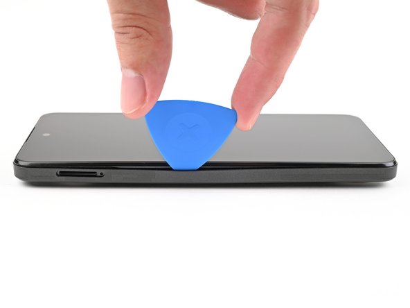
- Insert the tip of an opening pick between the back cover and frame at the SIM card tray cutout.
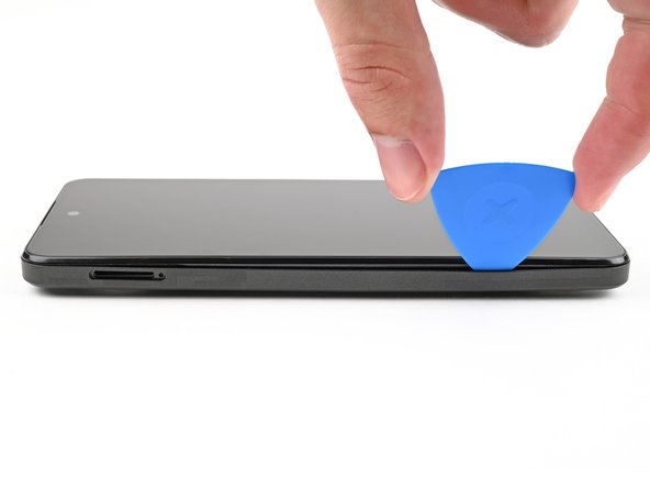
- Slide the opening pick along the left edge to begin unclipping the back cover.
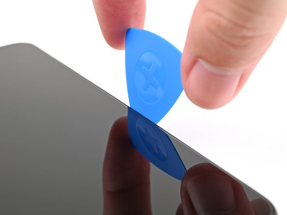
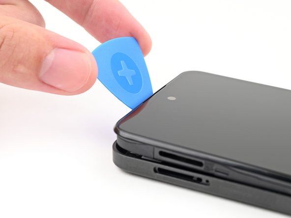
- Continue sliding the pick around the perimeter of your phone until the back cover is fully unclipped.
- The corners can be tricky to unclip and may take some force. If you're having trouble, try prying up with the pick.
- Don't try to fully remove the cover yet, as it's still connected by a delicate cable.
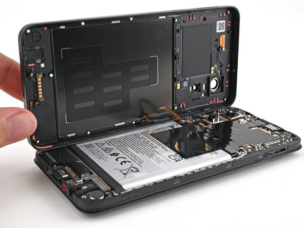
- Carefully flip your phone over so the back cover is facing up.
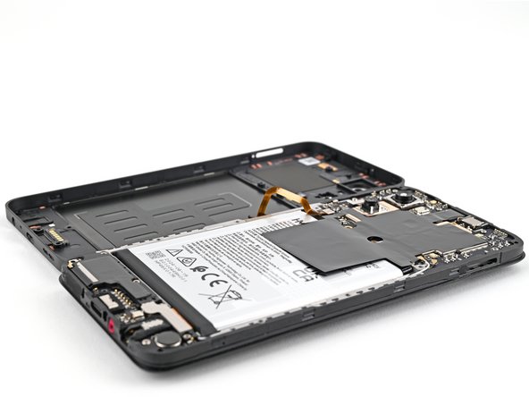
- Lift the back cover off the frame and flip it over the left edge of your phone, laying the cover flat on your work surface.
- Be very careful not to strain the back cover's delicate cable.
- During reassembly, place the back cover onto the frame and firmly press around the perimeter to reengage all the clips.
- Use a spudger to pry up and disconnect the battery press connector.
- Use a spudger to pry up and disconnect the power button press connector.
- Remove the back cover.
- Be careful not to puncture or damage the battery with your tool during the rest of this guide.
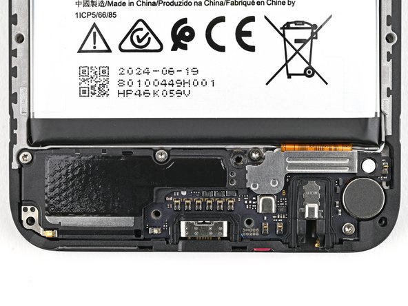
- Use a T3 Torx screwdriver to remove the three 3.4 mm‑long screws securing the loudspeaker.
- One of the screws on the loudspeaker may be covered by a sticker. Pierce through it with your screwdriver, or use tweezers to remove it.
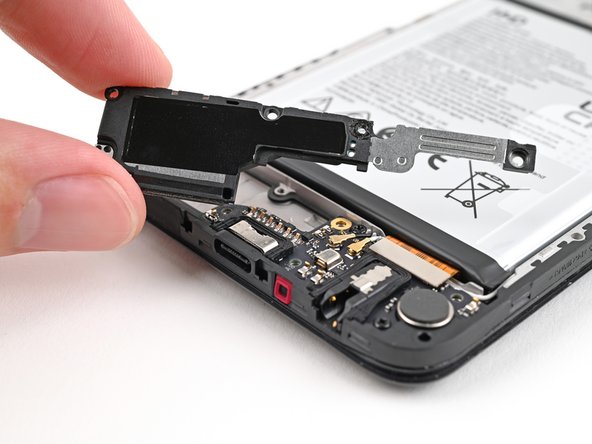
- Use your fingers to lift the loudspeaker out of the frame by its metal bracket.
- Remove the loudspeaker.
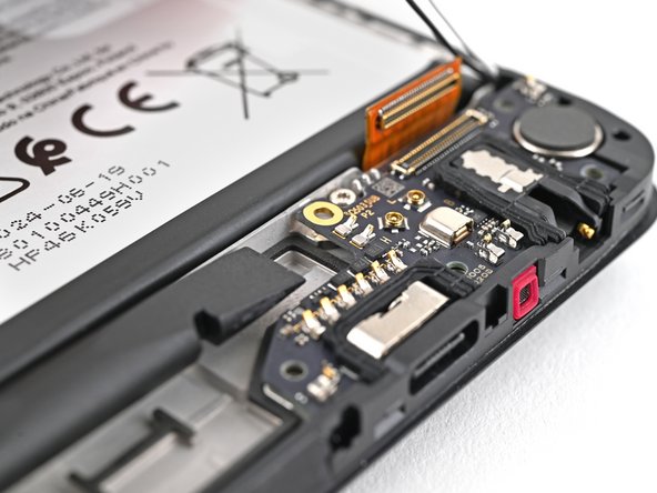
- Slide one arm of a pair of tweezers under the metal neck of the black antenna cable's connector head, near the center of the board.
- Lift straight up to disconnect the cable.
- Repeat for the white antenna cable.
- To reconnect the cable, hold the metal head over its socket and press down with the flat end of a spudger—it should snap into place. If it's not connecting, reposition the head and try again.
- Use a spudger to pry up and disconnect the interconnect cable press connector.
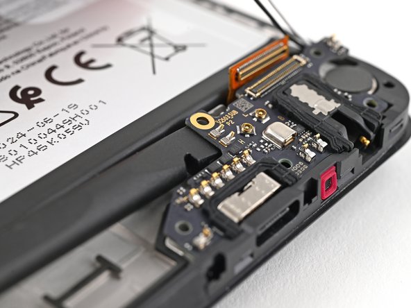
- Move the interconnect cable press connector toward the battery to keep it out of the way of the charging board in the next step.
- You can use tape with light adhesive (such as painter's tape) to keep the cable out of the way.
- Use tweezers, or your fingers, to move the two antenna cables out of their slots near the top edge of the charging board.
- Use a T3 Torx screwdriver to remove the 3.3 mm‑long screw securing the charging board.
- The top edge of the charging board is adhered to the frame.
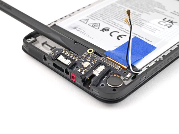
- Insert the flat end of a spudger under the top left edge of the charging board, next to the antenna cable connectors.
- Slide the spudger under the charging board to separate the adhesive.
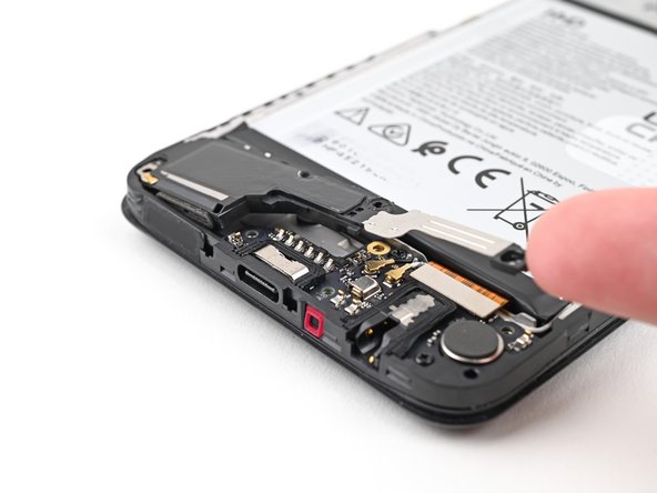
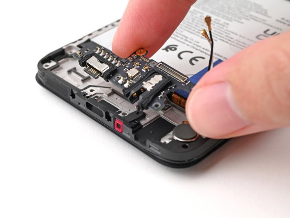
- Lift the charging board out of the frame and remove it.
- During reassembly, insert the USB-C port into its slot before pressing the charging board flat to the frame.