Logic Board Removal (Battery)
ID: 176342
Description: This guide shows how to remove the logic board...
Steps:
- Let your Pixel's battery drain below 25% before starting this repair. A charged lithium‑ion battery may catch fire if damaged.
- Unplug all cables and completely power down your phone.
- Adhesive secures the perimeter of the rear cover to the frame.
- When separating the adhesive, don't insert your tool more than 3 mm under the rear cover to avoid damaging the internal components.
- Measure 3 mm from the tip and mark your opening pick with a permanent marker. Alternatively, you can tape a coin to a pick 3 mm from the tip.
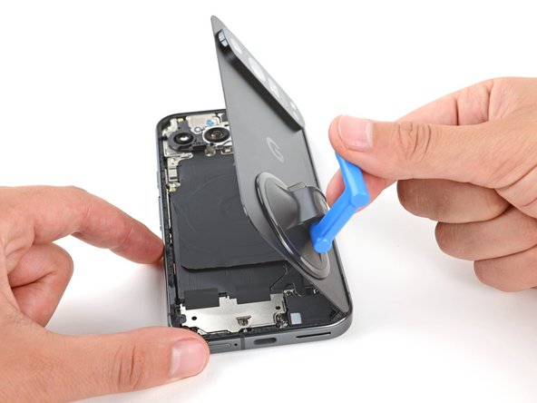
- Attach a suction handle to the bottom edge of the rear cover, as close to the edge as possible.
- Pull up on the suction handle with strong, steady force to create a small gap under the rear cover.
- Insert the tip of an opening pick in the gap.
- Slide your opening pick along the bottom edge to separate the adhesive securing it.
- Remember: don't insert the opening pick deeper than 3 mm.
- Slide your opening pick up the left edge and along the top edge to separate the adhesive.
- Slide your pick down the right edge to separate the remaining adhesive.
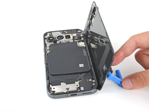
- Don't try to fully remove the rear cover yet, as a ribbon cable on the right edge connects it to the phone.
- Use the suction handle to lift the left edge of the rear cover and swing it over the right edge, like opening the cover of a book.
- If you're having trouble, check the perimeter for any remaining adhesive and use your opening pick to separate it.
- Prop up the rear cover with the suction handle so you can access the ribbon cable near the top right corner.
- Throughout this repair, keep track of each screw and make sure it goes back exactly where it came from.
- While the Pixel 9 Pro uses Torx Plus screws, standard Torx bits will also work. Make sure to apply constant, downward force to prevent stripping.
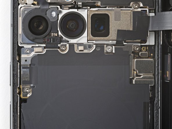
- Use a Torx Plus 3IP screwdriver to remove the five screws securing the wireless charging assembly:
- Four 5.4 mm‑long screws
- One 1.5 mm‑long screw
- This screw is non‑magnetic—you may need to use tweezers to remove it.
- Be very careful not to damage the spring contacts under the top left edge of the wireless charging assembly.
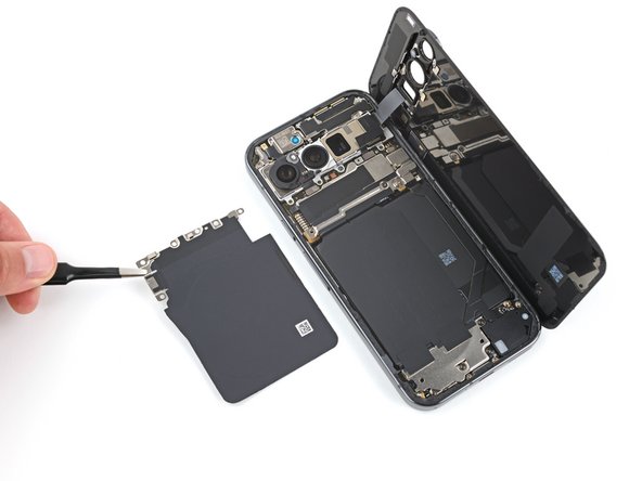
- Use tweezers or your fingers to remove the wireless charging assembly.
- Insert the tip of an opening pick under the left edge of the rear cover press connector and pry straight up to disconnect it.
- Remove the rear cover.
- During reassembly, follow this guide to apply new adhesive and install your rear cover.
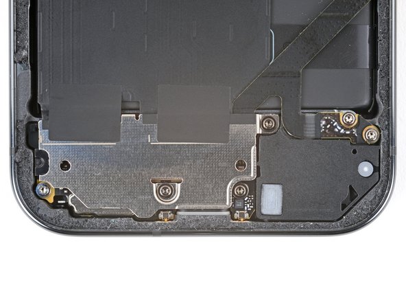
- Use a Torx Plus 3IP screwdriver to remove the two screws securing the cable cover:
- One 2.3 mm‑long screw
- One 5.4 mm‑long screw
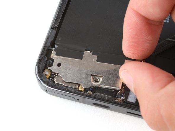
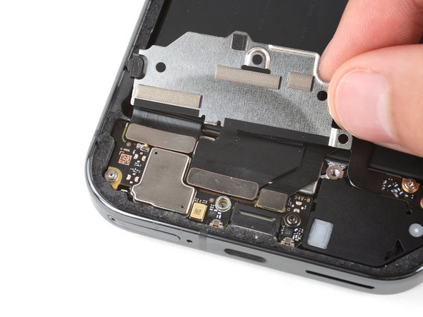
- Use tweezers or your fingers to remove the cable cover.
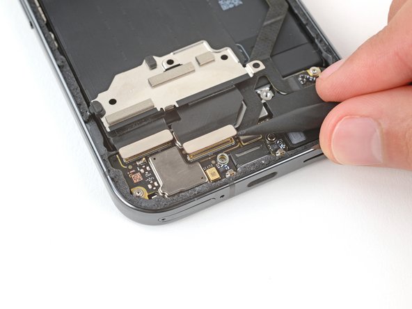
- Insert the point of a spudger under the right edge of the battery press connector and pry straight up to disconnect it.
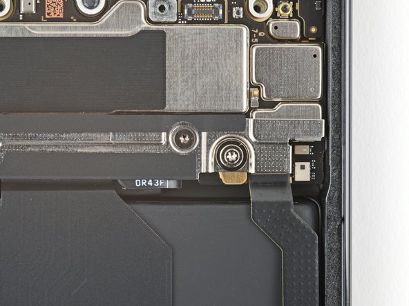
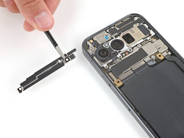
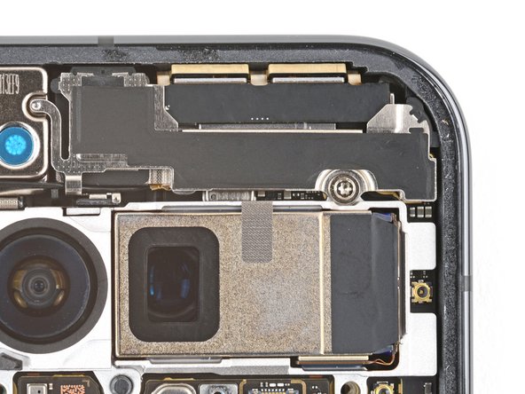
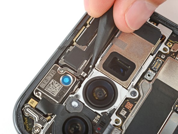
- Use a Torx Plus 3IP screwdriver to remove the 5.4 mm‑long screw securing the mmWave antenna cover.
- Insert the point of a spudger under the clip near the bottom left corner of the mmWave antenna cover and pry up to unclip it.
- Gently pull the right edge of the cover towards the bottom of the phone and remove the cover.
- During reassembly, insert the two tabs on the top corners under their recesses in the frame and push the cover down to clip it into place.
- Use the point of a spudger to pry up and disconnect the mmWave antenna press connector from the top right corner of the logic board.
- Use the point of a spudger to pry up and disconnect the front facing camera press connector.
- Be very careful not to touch the cameras during this step. If you accidentally do, wipe them with a clean microfiber or lint‑free cloth.
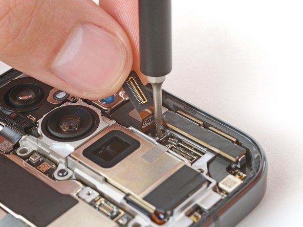
- Carefully hold the front facing camera cable out of the way so you can access the mmWave antenna screw.
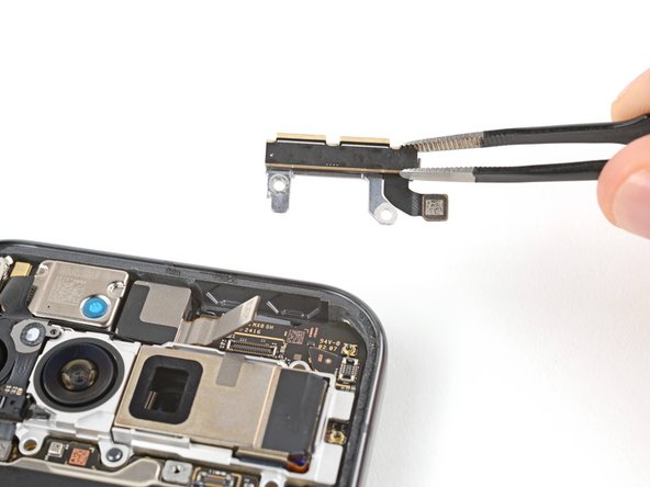
- Use a Torx Plus 3IP screwdriver to remove the 4.3 mm‑long screw securing the mmWave antenna.
- Use tweezers or your fingers to remove the mmWave antenna.
- During reassembly, make sure the mmWave antenna goes under the front facing camera cable.
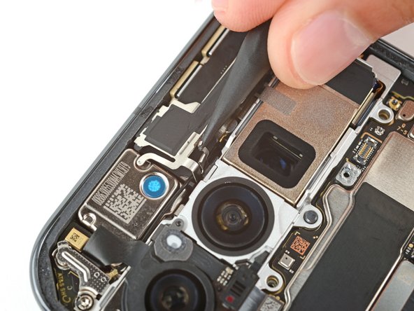
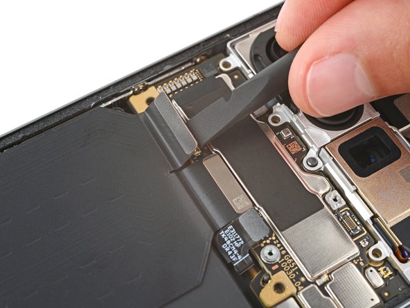
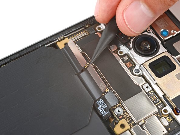
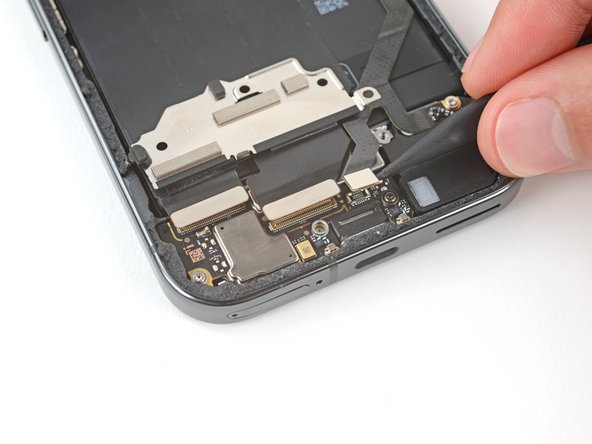
- Use the flat end of a spudger to pry up and disconnect the press connector near the bottom left corner of the logic board.
- Use the point of a spudger to disconnect the press connector just to the right of the previous one.
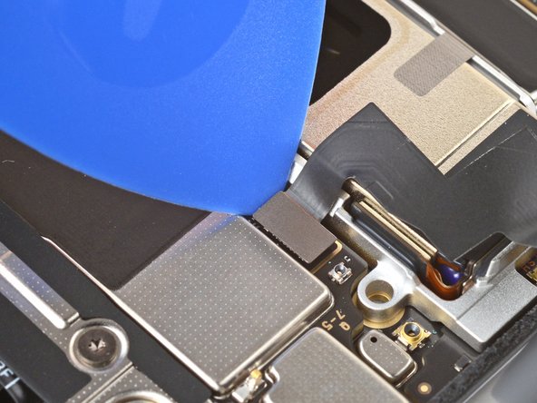
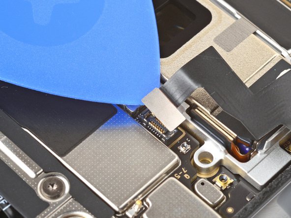
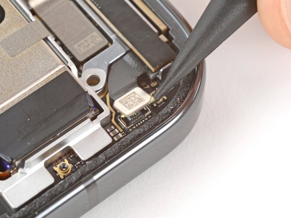
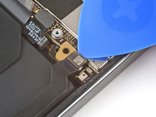
- Insert the tip of an opening pick under the top edge of the press connector near the bottom right corner of the logic board.
- Be very careful not to damage the small, surface-mounted components to the right of the connector.
- Use the pick to pry up and disconnect the press connector.
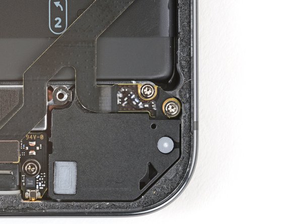
- Use a Torx Plus 3IP screwdriver to remove the two 4.3 mm‑long screws securing the charging board cover.
- Use your fingers to pull the right edge of the charging board cover towards the top of your phone to unclip the left side of the cover.
- Flip the cover away from the charging board so you can access its press connectors.
- Be very careful not to damage any of the small, surface‑mounted components on the charging board.
- Use the point of a spudger to pry up and disconnect the three press connectors on the top edge of the charging board.
- Use your fingers to remove the left interconnect cable.
- Use a Torx Plus 3IP screwdriver to remove the two 2.5 mm‑long screws securing the bottom of the right interconnect cable.
- Use your fingers to remove the right interconnect cable.
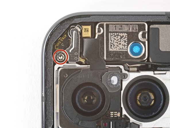
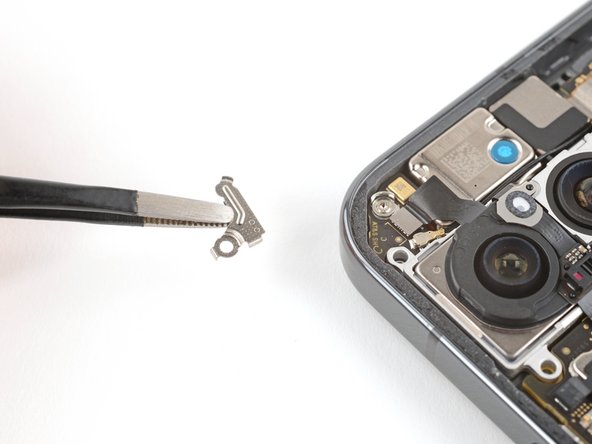
- Use a Torx Plus 3IP screwdriver to remove the 5.4 mm‑long screw securing the antenna cover in the top left corner.
- Use tweezers or your fingers to remove the cover.
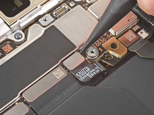
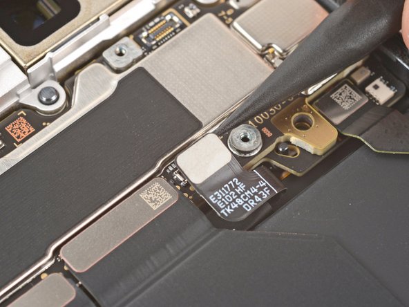
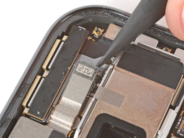
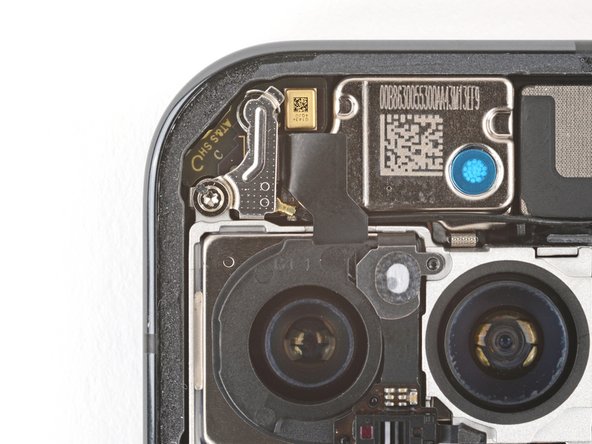
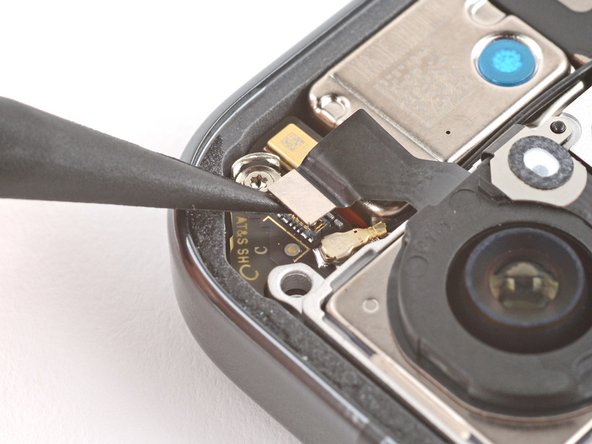
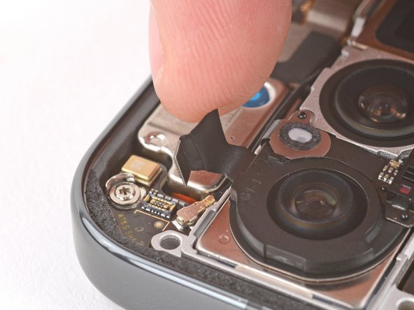
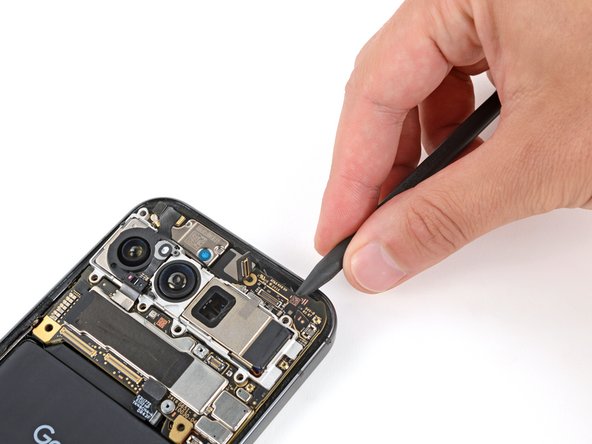
- Use the point of a spudger to pry up and disconnect the autofocus sensor press connector from the top left corner.
- Carefully move the cable out of the way so you can access the metal antenna connector underneath.
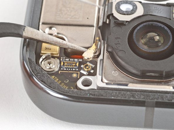
- Slide one arm of your angled tweezers under the metal neck of the antenna connector and lift straight up to disconnect it.
- To reconnect, hold the connector in place over its socket and gently press down with your finger or a spudger—the connector should "snap" into place. If you're having trouble, reposition the head and try again.
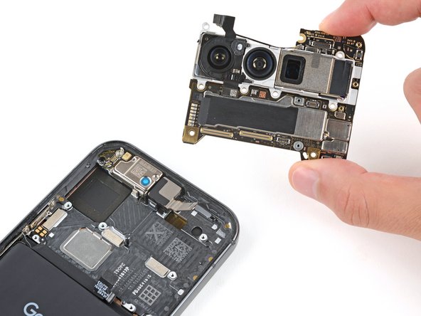
- Use a spudger to pry up the top edge of the logic board until you can grip it with your fingers.
- Grip the right side of the logic board and remove it, being careful not to snag the front facing camera and battery cables.
- During reassembly, hold the front facing camera cable out of the way and lower the logic board into place.
- During reassembly:
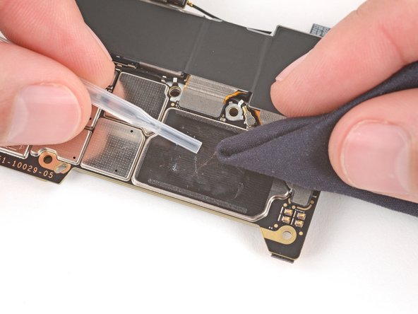
- Check the condition of the logic board thermal pad—it will either be on the bottom of the logic board or on the frame.
- If the pad is undamaged, skip the rest of this step.
- If the pad is damaged, use the flat end of a spudger to scrape it up and remove it.
- Use isopropyl alcohol (greater than 90%) and a microfiber cloth to remove all thermal pad residue from the frame and bottom of the logic board.
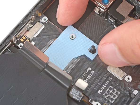
- Apply a new thermal pad to its spot on the frame.