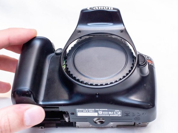
Canon EOS Rebel T3 Front Grip Replacement
ID: 178345
Description: This guide shows you how to replace the rubber...
Steps:
- Pry open the rubber I/F terminal cap with your finger.
- Remove the two M1.7x4.5mm JIS #000 screws that are underneath the I/F terminal cap.
- Using a plastic pick, or another thin plastic prying tool, pop off the I/F terminal cover from the camera.
- On the left side of the camera, remove the following screw:
- One M1.7x4.5mm JIS #000 screw
- On the right side, remove the following screws:
- One M1.7x5.5mm JIS #000 screw
- One M1.7x4.5mm JIS #000 screw
- Remove the battery door.
- Open the battery door to about a 35° angle.
- Pull the battery door straight outwards.
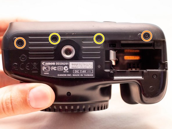
- Remove the following screws from the bottom of the camera:
- Two M1.7x4.5mm JIS #000 screws
- Two M1.7x3.0mm JIS #000 screws
- Carefully lift the back cover partially off of the camera.
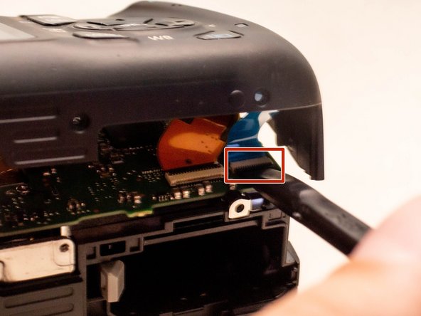
- There are two ribbon cables still connecting the back cover to the camera.
- Disconnect the right most ribbon cables from the main PCB board.
- Use a plastic spudger to lift up the black locking tab.
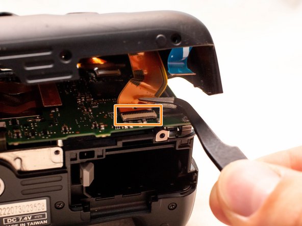
- Pull out the ribbon cable from its connector using a pair of angled tweezers.
- With this ribbon cable disconnected, you will be able to move the back cover slightly farther away from the camera, giving you more room to remove the remaining ribbon cable.
- Remove the left ribbon cable using the same two steps as with the other ribbon cable.
- Remove the following screws on the front of the camera.
- Two M1.7x5.5mm JIS #000 screws
- On the bottom of the camera, remove the following screws:
- Two M1.7x5.5mm JIS #000 screws
- One M1.7x4.5mm JIS #000 screw
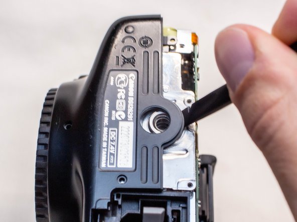
- Slide a spudger tool towards the tripod mount, underneath the plastic cover.
- Push the plastic cover up and over the tripod mount.
- Pull the front cover off of the camera.
- Electric Shock Warning: With the front cover off, the high voltage capacitor on the DC PCB board is now exposed. It is recommended that you use a capacitor discharge tool to ensure the capacitor is fully discharged before proceeding further.
- Remove the two 4.5mm JIS #000 screws on the backside of the front cover.
- Slide the grip forward and off of the front cover.