Lenovo ThinkPad X280 Motherboard Replacement
ID: 178670
Description: Follow this guide to safely remove and replace...
Steps:
- To begin, ensure that the device is powered off and not plugged into a energy supply.
- Open the device to where you are directly viewing the screen with the keyboard laying flat.
- Using the flat end of the spudger, insert it at the top of the right click button.
- Pry it up to remove the button.
- Repeat for the left click button.
- Use the Phillips #0 screwdriver to unscrew the two 5 mm captive screws.
- Using the black spudger tool, gently lift under the plastic where the screws were located.
- Slide the keyboard towards the screen of the LenovoThinkPad X280 and lift the front edge by hand.
- Gently remove the keyboard from the device and flip it over.
- It should still be attached with connectors on the far left corner at the top so be careful not to rip or pull the keyboard out.
- Disconnect the keyboard and trackpad cables locks with the pointed end of the black spudger.
- Gently pull the cables from the rectangular connection site to detach the keyboard.
- Remove the keyboard.
- To begin, ensure that the device is completely powered off and not connected to an energy supply.
- Close the device and flip it over to expose the back panel.
- Use a Phillips #1 screwdriver to unscrew the five captive screws on the back panel until a small pop is heard.
- These are captive screws and do not come out completely.
- Gently wedge an opening tool or spudger under the back panel, and loosen the clips around the perimeter until the back panel comes off.
- Remove the back cover.
- Using the Phillips #1 screwdriver, remove the four 5 mm screws that are holding the battery down.
- Remove the battery.
- Push in with a SIM ejector tool, and while pushing, pull the tray out.
- Some cheap ejectors are too short.
- use a screwdriver or a spudger to flip up the two black ZIF locking flaps that secure the ribbon cables.
- Disconnect the two ribbon cables.
- Carefully use a spudger or a screwdriver to flip up the two locking flaps the metal retaining clips and disconnect the two ribbon cables from their sockets.
- Use a Phillips #1 screwdriver to remove the single 3 mm screw securing the Wi-Fi card.
- Gently pull the Wi-Fi card out of its slot at an angle to prevent damage to the connectors.
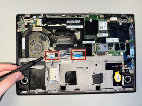
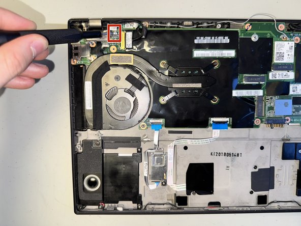
- Use nails or a spudger to gently disconnect the first two plastic connectors from the motherboard by carefully pulling each one straight out of its socket.
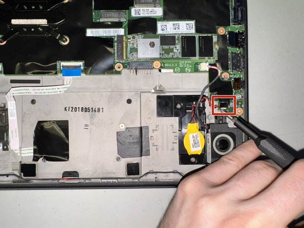
- Disconnect the power button (third picture) with a spudger by nudging it, alternating on right and left sides, until it can be pulled out.
- This is the most difficult part of this guide, it is finicky.
- Avoid applying excessive force to prevent damage. Do not pull on the cables themselves!
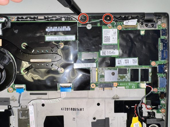
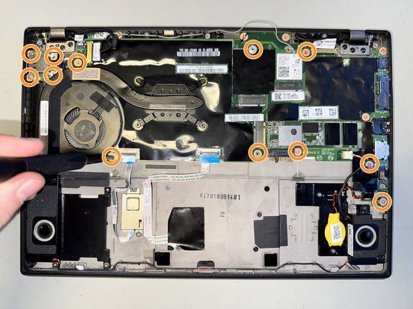
- Remove the four 5.4 mm screws securing both the metal and plastic covers using a Phillips #1 screwdriver.
- Gently lift and remove the covers to expose the internal components.
- Unscrew the remaining fourteen 3.4 mm screws using a Phillips #1 screwdriver.
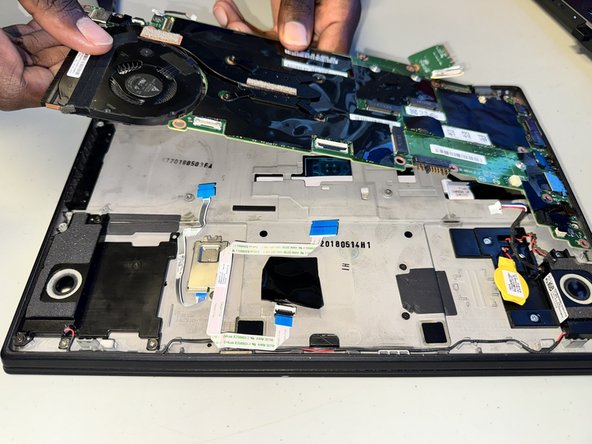
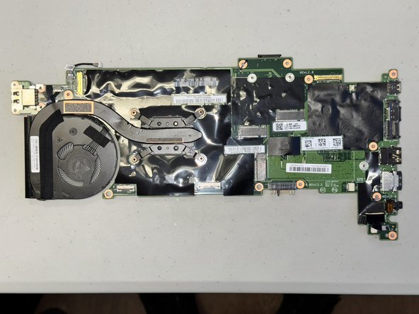
- Carefully lift the motherboard by gently bending it to release it from its secured position.
- Once it is loose, pull it out and away from the case, ensuring all connectors and screws are detached to avoid damage.