iPhone 16 Pro Max Logic Board Removal
ID: 181162
Description: Steps to remove the logic board for the iPhone...
Steps:
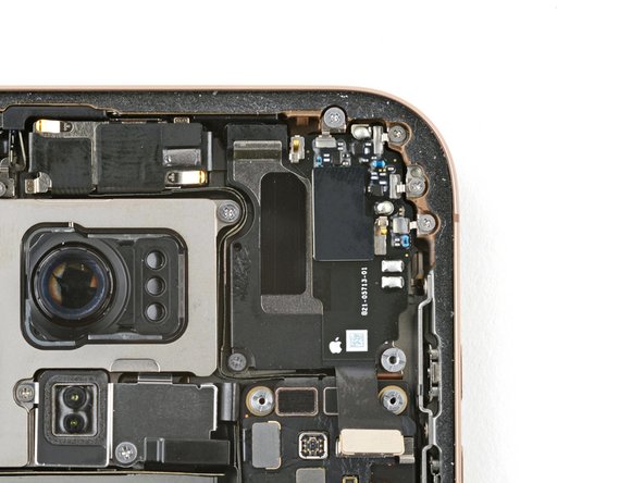
- Use the point of a spudger to pry up and disconnect the earpiece speaker and 5G mmWave antenna press connectors.
- Remove the six screws securing the earpiece speaker:
- One 2.4 mm‑long Phillips screw
- Three 1.3 mm‑long Phillips screws
- One 1.6 mm‑long Phillips screw
- One 3.3 mm‑long standoff screw
- Standoff screws are best removed using a dedicated standoff driver or driver bit. In a pinch, a small flathead screwdriver will do the job—but use extra caution to ensure it doesn't slip and damage surrounding components.
- Use tweezers to lift and remove the earpiece speaker.
- You may feel some resistance near the top edge, where the speaker gasket seals against the frame. Pull the speaker out gently to release the seal.
- Use a spudger to pry up and disconnect the seven silver press connectors from the top of the logic board.
- Use a spudger to pry up and disconnect the three black press connectors from the logic board.
- Use a standoff driver to remove the four screws securing the logic board:
- Two 4.5 mm‑long screws
- One 3.4 mm‑long screw
- One 4.2 mm‑long screw
- This image shows the display connector underneath the logic board. The next two steps show how to disconnect this connector from the bottom of the logic board.
- If your iPhone has a physical SIM tray, eject it before you proceed.
- Make sure all the connectors are disconnected from the top of the logic board.
- Insert the flat edge of an opening pick between the battery and the left edge of the logic board. Hold the pick in place with your fingers.
- Insert the flat end of a spudger underneath the right edge of the logic board.
- Gently pry with the spudger to lift the logic board and disconnect the display connector.
- Don't remove the logic board yet. There's still a cable connected to the bottom side.
- Flip the logic board over, being careful not to strain the connected cable.
- Use the point of a spudger to pry up and disconnect the front sensor connector from the bottom side of the logic board.
- Remove the logic board.