iPhone 16 Pro Max Logic Board Installation
ID: 181163
Description: Installation steps for installing a logic board...
Steps:
- Hold the logic board so that the front sensor cable is close to its connector.
- Align the front sensor cable connector carefully over its logic board socket.
- Use the point of a spudger or your finger to press the connector until it clicks into place.
- Don't try to force the connector into place. If you're having trouble, reposition it and try again.
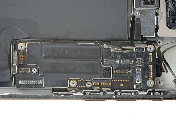
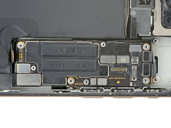
- Gently bend all the loose press connectors out of the way so you can lay the logic board in place.
- Lay the logic board in its recess.
- You can't directly connect the display connector to the bottom of the logic board without removing the screen, but you might successfully connect it by screwing the logic board in place. Be sure to test your iPhone before you seal it up.
- Make sure the logic board rests in place against its screw posts. The posts will properly align the board to the display connector underneath it.
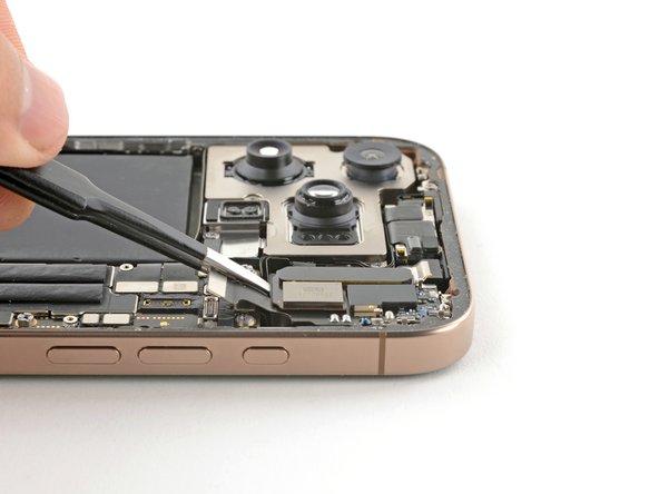
- Use a standoff driver to install the four screws securing the logic board:
- Two 4.5 mm‑long screws
- One 3.4 mm‑long screw
- One 4.2 mm‑long screw
- Use your finger or a spudger to press and connect the three black press connectors onto the logic board.
- To re-attach press connectors like these, carefully align and press down on one side until it clicks into place, then repeat on the other side. Don't press down in the middle. If the connector is misaligned, the pins can bend, causing permanent damage.
- Use your finger or a spudger to press and connect the seven silver press connectors onto the logic board.
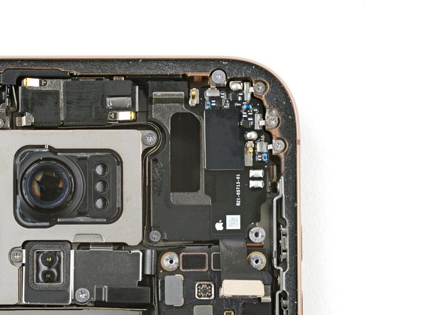
- Align the top edge of the earpiece speaker with the top edge of the frame.
- Lay the earpiece speaker into its recess.
- You may need to push the speaker towards the top edge of the frame to seat it properly.
- Install the six screws securing the earpiece speaker:
- One 2.4 mm‑long Phillips screw
- Three 1.3 mm‑long Phillips screws
- One 1.6 mm‑long Phillips screw
- One 3.3 mm‑long standoff screw
- Use your finger or a spudger to press and connect the earpiece speaker and the mmWave connectors onto the logic board.