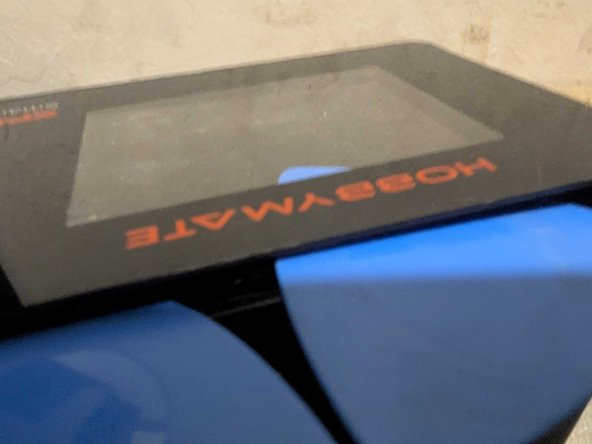
Hota H6 Pro Battery Charger Disassembly & AC Fuse Replacement
ID: 181696
Description: The Hota H6 Pro also sold as the Hobbymate...
Steps:
- Be sure to unplug power and all batteries before starting.
- Keep ALL power sources away until the charger is fully reassembled. I destroyed my unit by plugging in a battery too early.
- Insert a pick above the DC IN plug
- Pry pick down to slightly raise the top plate above the body
- Insert a second pick in the gap between the faceplate layer and the plastic frame below
- Work the pick all the way around the edges of the faceplate with a rocking motion to separate the glue.
- Slowly peel the faceplate off and keep it somewhere safe so the glue doesn't get dirty
- Remove the 4 small screws in the corners
- Starting at the side with the screen, use a pick around the edge to lift the plastic lid.
- Lift the lid plate straight up along with the fan.
- Be firm but gentle - there are thin ribbon cables connecting the display and green board to the circuit below.
- Pull the top plate horizontally away from the fan.
- The fan is friction fit onto the two plastic pins on the top plate
- Remember not to tug hard on the ribbon cables.
- Lift the tiny black hinged clamps on the ribbon cable connectors for the display and green circuit board.
- Use tweezers to slide the ribbon cables horizontally back out of the connector slots.
- For re-assembly make sure the end of the ribbon cable lies flat in the connector before pushing the stiff part of the ribbon cable further in with the tweezers. Use another finger or tool to close the black clamp while you hold the cable
- Remove top plate.
- Pull out fan - it will be attached by long wires.
- Remove the two small black screws holding the upper circuit board down.
- Slightly lift up on the side of the circuit board by the fan
- Slide the circuit board out at this angle to avoid bending the battery balance connector pins
- Remove the 3 screws holding the heat sink to the back of the circuit board
- This unlabeled chip (yellow arrow) gave up the smoke when I tried to power the DC Input before fully reassembling the unit. - Don't try it!
- WARNING dangerous voltages may still be present in this part of the circuit even after unplugging everything. Especially capacitors shown in red. ASSUME any exposed metal here could shock you like a wall outlet and take appropriate safety measures like gloves and/or shorting the terminals of these capacitors.
- Slide the AC power socket up and out of the case.
- Remove the 4 corner screws holding Down the AC high voltage PCB
- The two fuses shown here can be Desoldered and replaced if needed.
- Test the fuses by using a multimeter to probe the resistance between the pairs of pins (shown in green) on the underside of the circuit board. Working fuses should be near zero resistance. Broken fuses will show 'infinite' resistance.
- Neither fuse was blown in my unit, so the problem was elsewhere. These fuses seem more likely to prevent a fire and may not save the charger from overload damage. Your milage may vary...
- Fully disassembled