Pentax ZX-5n Shutter Unit Replacement
ID: 181726
Description:
Steps:
- Push down on the screw to depress the spring loaded hinge and release the door.
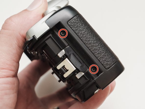
- Remove six 5.3 mm #00 screws.
- Remove one 3.4 mm #00 screw.
- The short screw has a machine thread and screws into the plate underneath. The rest screw into the plastic body.
- Remove three 5.3 mm #00 screws (the bottom-most screw is not always present).
- Remove one 7.3 mm #00 screw.
- Remove the remote trigger cover.
- Remove one 3.4 mm #00 screw.
- Remove two 5.3 mm #00 screw.
- Gently lift up on the flash housing to help remove the cover if necessary.
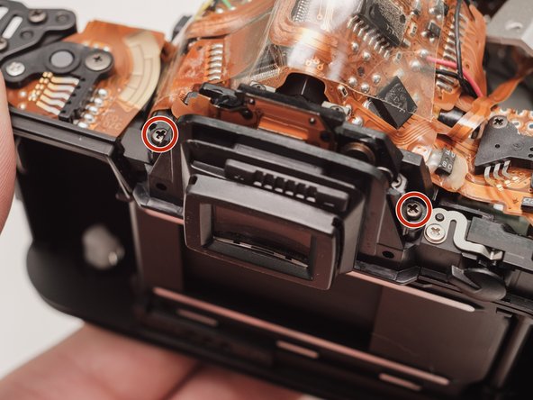
- Remove two 3.9 mm #00 screws.
- Slide the eye cup up and off to access the screws underneath.
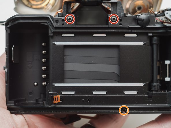
- Remove two 5.3 mm #00 screws by the eyepiece.
- Remove one 6.8 mm #00 screw in the battery compartment.
- Remove one 7.0 mm #00 screw near the take up spool.
- Lift the cover so it is just free of the body. It is still attached by several wires.
- Use a 1kΩ-10kΩ resistor to discharge the capacitor. Place the resistor between the blue wire, exposed in the previous step, and ground.
- The flash capacitors store energy at a very high voltage. Failing to discharge the capacitors properly could result in personal injury and/or damage to the camera.
- Unsolder one green wire.
- Unsolder one blue wire.
- Unsolder one brown wire.
- Unsolder one black wire.
- Unsolder one black wire.
- Pull black wire out from its routed location.
- Unsolder flex connector
- Be careful not to overheat the flex circuit. Work in short durations. Allow for cool downs in between if necessary.
- Some repairs can be performed with the top cover still connected but the flex connection is fragile and easily damaged.
- De-solder the indicated joints. Use a solder sucker on the tabbed connections.
- Pull the black wire from the battery flex to get more slack in the connection to the top cover.
- Be careful not to overheat the flex circuit. Work in short durations. Allow for cool downs in between if necessary.
- Use a solder sucker to de-solder the four posts from the flex circuit.
- This is the most difficult part of the repair. Patience and persistence are required.
- Be careful not to overheat the flex circuit. Work in short durations. Allow for cool downs in between if necessary.
- Unsolder film advance motor connections.
- Unsolder sprocket counter connections.
- Unsolder power and ground connections.
- Unsolder panorama switch connections.
- Be careful not to overheat the flex circuit. Work in short durations. Allow for cool downs in between if necessary.
- Remove one 4.3 mm #00 screw.
- Gently pry up the plastic carrier under the flex circuit. It may catch slightly on the battery contact tab.
- Pay close attention to the connections around the four through-hole posts as you lift the flex. Make sure that no solder is left over and that it pulls away freely.
- This metal tab is lightly held in place with lacquer and can easily come loose. Keep an eye on it.
- Remove one 3.3mm #00 screw.
- Remove one 3.9 #00 screw.
- De-solder the red wire.
- Peel off the black tape. Leave it attached to the wires.
- Gently peel the flex circuit from the surface of the capacitor.
- There may be additional adhesive underneath the larger capacitor.
- Lift the two capacitors and the flash PCB out as a single unit.
- The double sided tape used to secure the capacitors can be softened with isopropyl alcohol if necessary.
- Remove two 3.4 mm #00 screws. Remove the plate holding the contacts in place.
- Peel tape from the plate. Leave the tape attached to the flex circuit.
- Remove the flex circuits from their retaining studs.
- Remove one 3.3 mm #0 countersunk screw.
- Remove one 3.9 mm #0 shoulder screw.
- Remove four 3.3 mm #00 screws.
- Pull a little slack through the housing on this flex cable.
- Pop the plate off its posts, rotate slightly clockwise and pull gently through the loosened flex cable.
- To the camera tech that left me a happy little note...I see you.
- It's best to remove these parts now so they don't fall out later on in the repair.
- Remove one 3.8 mm #00 screw.
- De-solder the connections.
- Lift the flex off the retaining studs.
- Be careful not to overheat the flex circuit. Work in short durations. Allow for cool downs in between if necessary.
- Remove two 5.3 mm #0 screws.
- Remove two 7.4 mm #0 screws.
- Remove one 8.3 mm #0 screw.
- Remove one 3.3 mm #00 screw. The metal bracket will be loose and should be removed as well.
- Push the front housing block slightly up then lift the left side up and away from the housing.
- Proceed slowly and watch for any components that are catching. The right side is still attached by a large flex cable.
- There may be shims at the mounting points of the front housing block.
- Note the positions and remove if loose.
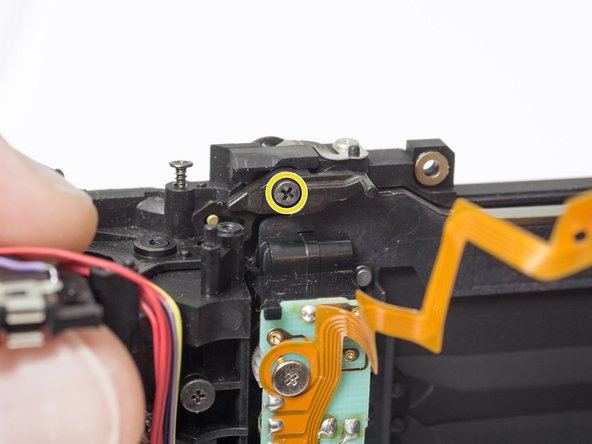
- Remove one X mm #00 screw.
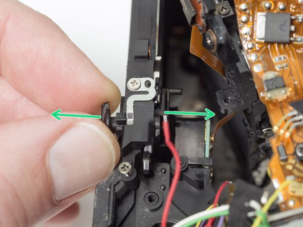
- Remove panorama switch contact.
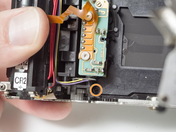
- Remove one X mm #00 screw.
- Pull panorama switch apart and remove both pieces.
- Remove one X mm #00 screw.
- Remove two X mm #00 screw.
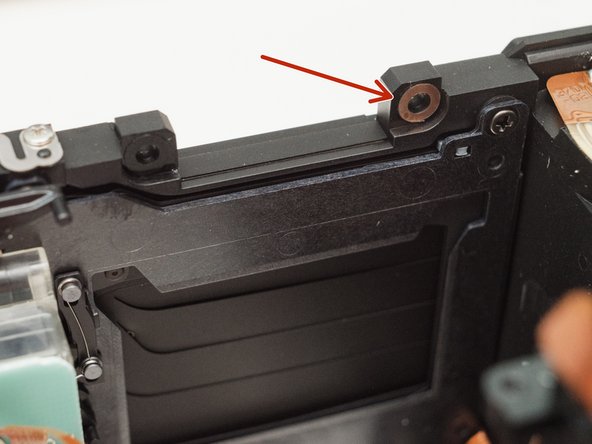
- Remove shutter unit.