Right Joy-Con Teardown
ID: 181748
Description: This guide aims to show how to completely...
Steps:
- Remove the four Tri-Point Y00 screws
- Remember to organize your screws as the Joy-Con uses many differently sized screws
- To separate the shell halves there are two options:
- 1. Use an opening pick and insert it between the IR sensor and the other half, carefully prying them apart
- 2. Push up on the rail towards the shell half not attached to the IR sensor
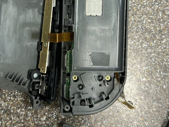
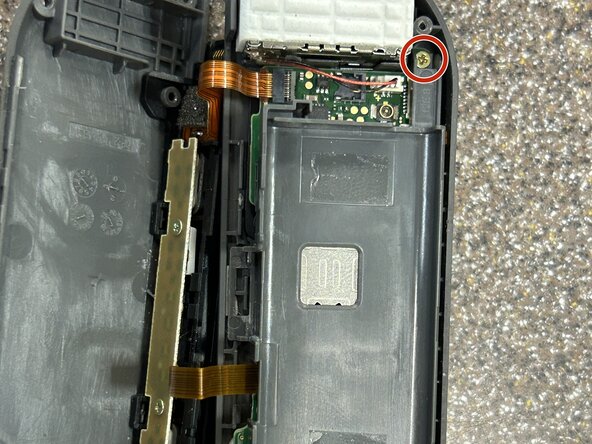
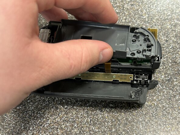
- With the shell halves separated, carefully put the side with the rail next to the other half
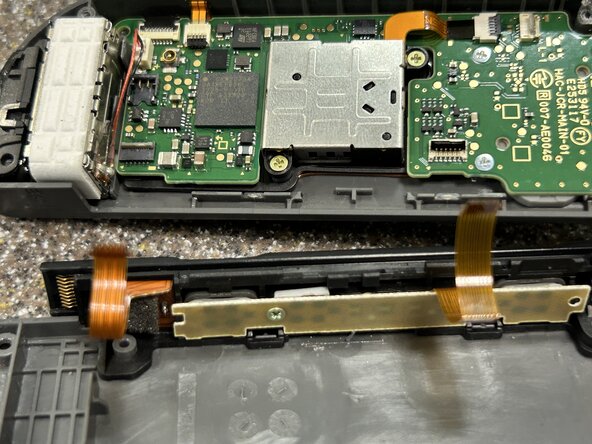
- There are two ribbon cables connecting the half with the rail to the other side
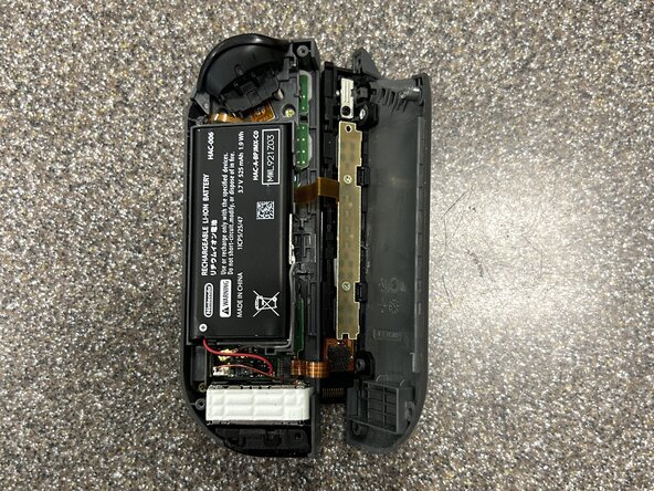
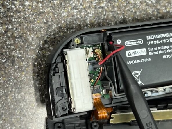
- Next, carefully disconnect the battery from the Joy-Con using a spudger
- With the battery disconnected, disconnect the Bluetooth antenna and pull it out of its compartment carefully
- Using an opening pick or the flat side of a spudger, pry up the battery from beneath it.
- There is some light adhesive holding down the battery which may require some force to overcome
- Take care not to puncture the battery. Try prying up the battery from one side and using the angle to pull it off the adhesive. If this does not work, use some isopropyl alcohol to soften the adhesive
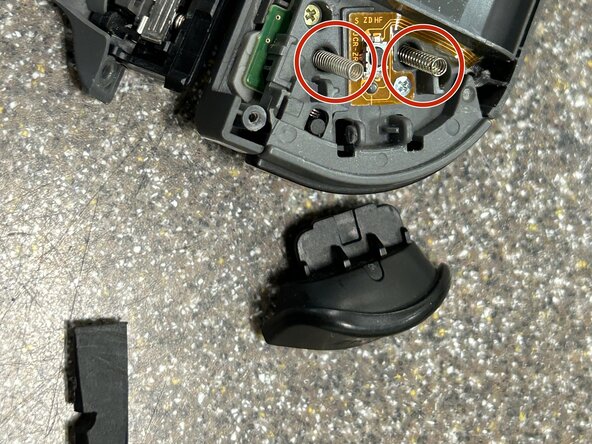
- Insert the flat side of a spudger or an opening pick between the ZR button and the upper bracket. Lift up on the ZR button until the clips disengage and you can carefully remove it.
- There are springs beneath the ZR button. Make sure to disengage the clips and remove the button carefully and slowly as the two marked springs will want to fly out
- Carefully remove the two springs
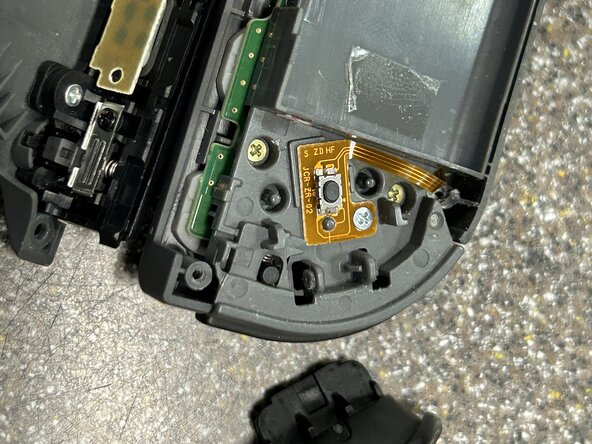
- Using a Phillips PH000 screwdriver, remove the screw holding down the flex cable and button
- Lift up the flex cable and button board using a spudger to disconnect it from the bracket
- Remove the three Phillips PH000 screws holding down the upper bracket and pull the bracket off the motherboard
- Make sure not to damage the free ZR trigger button flex cable as you pull up the bracket
- Flip up the ZIF connector lock holding in the ZR trigger button cable with the tip of a spudger and remove the flex cable
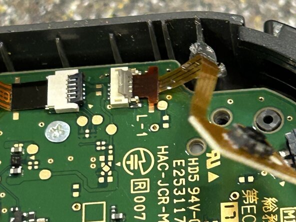
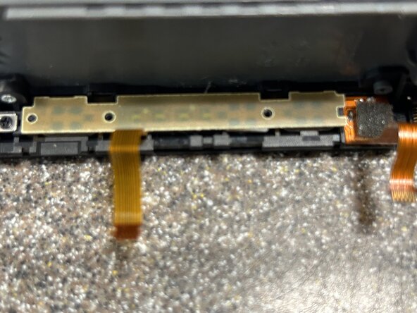
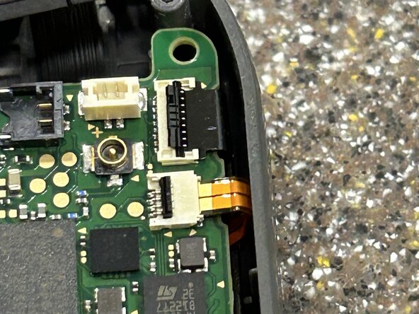
- Flip up the ZIF connector locks holding in the rail ribbon cables and remove the flex cables
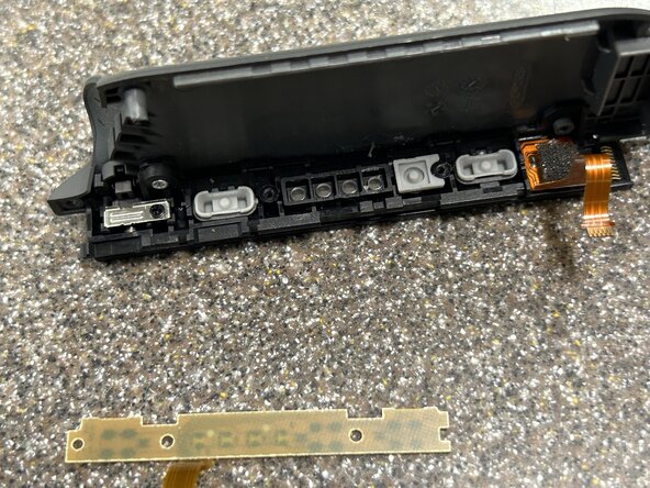
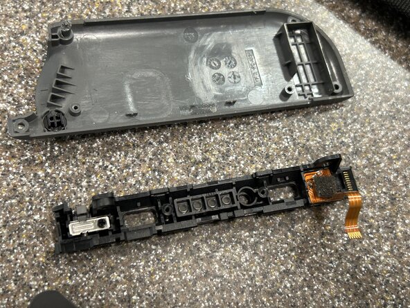
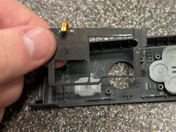
- Working on the charging rail, remove the two Phillips PH000 screws holding down the buttons
- Though there are three holes on the Joy-Con rail, only two are used for screws
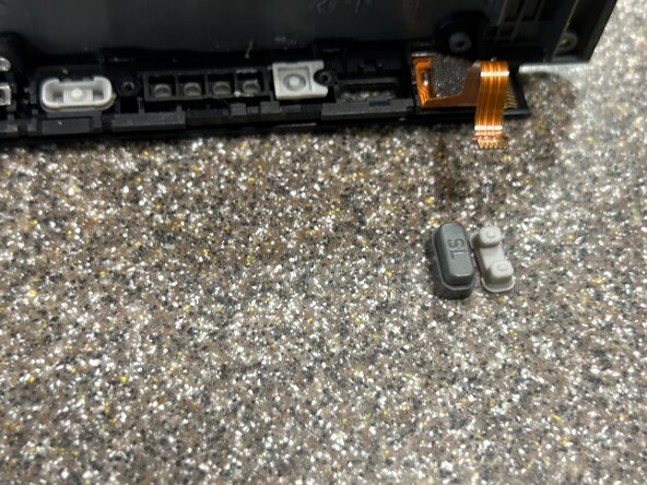
- Remove the rubber button backings and the plastic buttons
- Remove the Phillips PH000 screw holding the rail to the back shell
- Remove the last Phillips PH000 screw in the rail holding down the buckle lock
- See also Joy-Con Buckle Lock Replacement
- Concluding our time with the rail, remove the lock button from the shell
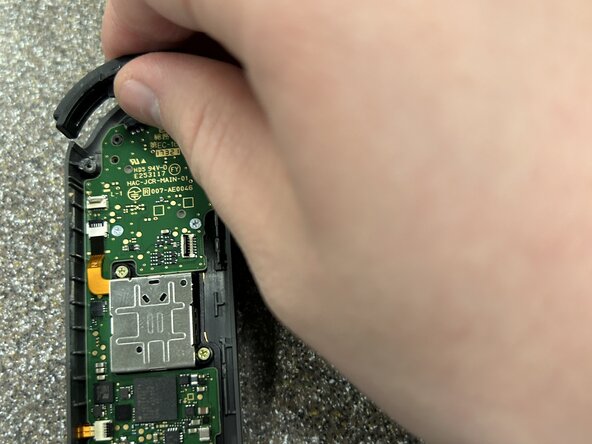
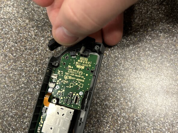
- Carefully remove the R button by pulling it up and out of the upper chassis
- Be wary of the spring here and ensure it does not fly off into the abyss
- Flip the ZIF connector for the analog stick and pull out the cable
- Note for reassembly: this is tricky to get back in. Notice the angle the ribbon cable is at and attempt to get the same angle as you prepare to reinsert the cable into the ZIF connector
- Remove the two Phillips PH000 screws holding down the analog stick
- Remove the analog stick carefully
- Do not pull out the joystick quickly or with extreme force! There is a liner underneath the analog stick that it will likely get caught on which protects the internals from dust and debris. Wiggle out the analog stick carefully lining up the stick center to the liner and using light force
- Carefully remove the analog stick liner by pulling up on it with tweezers and lightly pulling on the sections adhered to the upper chassis
- One of the adhered sections is under the motherboard of this controller so be patient removing the liner
- Note for reassembly: Try reattaching this when the mainboard is not connected as it is difficult to get one of the adhered sections under the mainboard
- Flip up one of the ZIF connectors
- Note for reassembly: These two ZIF connectors should be connected before screwing back in the mainboard as it is a royal pain to line up the cables and connectors when screwed on
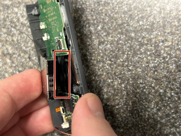
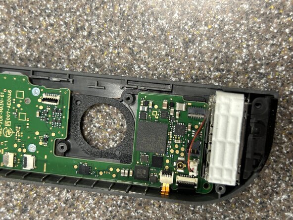
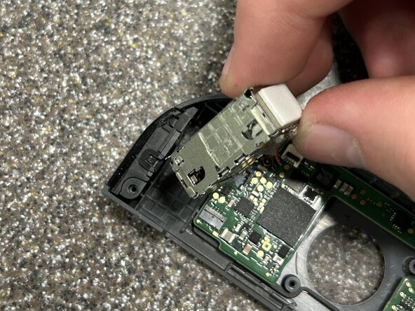
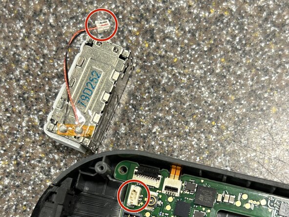
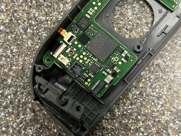
- Remove the rumble module by prying up on the corner next to where the rail once was with a spudger. Once out of its socket, use tweezers to pull the cable connector out of the socket. It is inserted quite firmly so be careful not to damage the cable and use your fingernails if needed
- There is some mild adhesive holding down the rumble module so take care not to damage it. Additionally, do not remove it fast enough to damage one of its connecting cables if it suddenly breaks free
- Carefully pull the IR sensor out of its socket making sure not to tear the flex cable connected to it
- Remove the final two Phillips PH000 screws holding down the motherboard
- Flip the final ZIF connector, detach both cables, and remove the motherboard
- Carefully remove the IR sensor
- The flex cable is lightly adhered to the chassis of the controller so make sure not to use excessive force or tear it
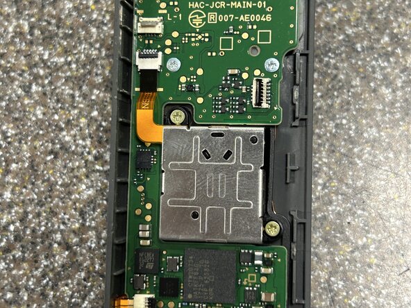
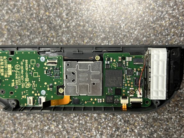
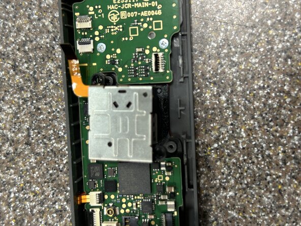
- Remove the adhered NFC reader by prying up on an edge carefully and pulling up on other areas until it can be safely removed (marked is the corner you could pull up from)
- The wires on the NFC reader are not protected from poor attempts to lift up this piece. Use your eyes, good judgement, and great care not to damage this component
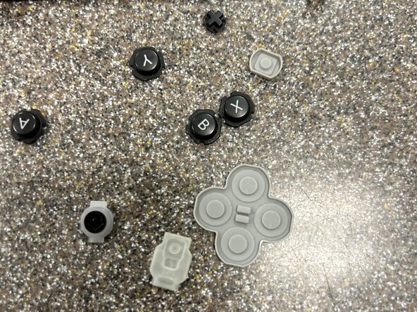
- Complete this teardown by removing the buttons and their rubber covers