How to Replace the Thermal Putty & Thermal Paste in your Xbox Series X
ID: 181894
Description: Use this guide to replace the thermal putty and...
Steps:
- Before you begin, completely power down and unplug all cables from your console.
- Use a pair of tweezers to remove the sticker hiding the first screw on the back panel, near the base.
- For cleaner removal, use an iOpener or hair dryer to heat the sticker.
- Use a pair of tweezers or a sharp blade to peel up a corner of the large sticker on the back panel. Use your fingers to peel it farther, just enough to reveal the second screw.
- You only need to peel this sticker to where you can access the hidden screw. You don't need to pull it completely off.
- Technically, these are tamper-evident stickers, but don't worry—Microsoft can't legally void your warranty, as long as you don't damage anything. Have fun!
- Use a T8 Torx driver to remove the two 7.4 mm‑long screws securing the back panel.
- Throughout this repair, keep track of each screw and make sure it goes back exactly where it came from to avoid damaging your console.
- Insert the flat end of a spudger into the gap between the back panel and the shell, near the left side of the base.
- Pry up the back panel to release it from the locking clips.
- Insert the flat end of a spudger into the gap between the back panel and the shell, near the right side of the base.
- Pry up the back panel to release it from the locking clips.
- Grip the back panel at the opening you just created and pull it up and away from the shell to unclip the long edges.
- During reassembly, press along the edges of the back panel to snap it into place.
- The back panel slots into a gap at the top of the shell.
- Tilt the back panel up and pull it away from the top edge of the shell to release it from the gap.
- Remove the back panel.
- Use a T8 Torx driver to remove the three screws securing the fan to the center chassis:
- One 10.5 mm pancake screw
- Two 8.8 mm screws
- Use your fingers or a pair of blunt tweezers to grip the edges of the fan cable connector, and pull up to disconnect it from the center chassis.
- Always pull cables by their connectors and not the wires themselves.
- During reassembly, route the fan cable underneath its small cable guide on the fan housing so it doesn't interfere with the back panel.
- Slide the fan out of its slot to remove it.
- During reinstallation, note that the fan can only be installed one way—make sure Master Chief is facing you.
- If you're replacing the fan, a new fan might not include the plastic installation bracket, which is attached to the fan with four T10 Torx screws. This isn't pictured in this guide.
- Use the flat end of a spudger to lift up on the locking tab holding the base to the shell.
- Grip the base and rotate it counterclockwise to unlock it from the shell.
- You may need to hold the locking tab open while you get the base started.
- Remove the base.
- During reassembly, drop the base tabs into their holes on the shell and twist clockwise until the base snaps into the interior locking tab.
- When locked in place, the "Hello from Seattle" line will be parallel with the device's sides.
- Use a T8 Torx driver to remove the two 8.8 mm screws securing the optical drive's vibration isolator to the shell: one on the base and one on the top of the isolator.
- Lift up the optical drive's vibration isolator to remove it.
- The vibration isolator grips the sides of the optical drive with silicone pads, so you may need to "walk" the isolator off of the drive to slip it off each side.
- During reassembly, ensure the vibration isolator is pushed down and around both edges of the optical drive, so it sits flush with the rest of the center chassis.
- Use a pair of blunt tweezers to grip the edges of the optical drive power connector and pull up to disconnect it from the optical drive.
- Always pull cables by their connectors and not the wires themselves.
- Use your fingers to pull up and disconnect the data cable from the optical drive.
- Grip the top edge of the optical drive and pull it out of its slot in the shell to remove it.
- During reassembly, align the pegs on the bottom edge of the optical drive with the guide holes on the bottom of the shell.
- If the drive is misaligned, the top vibration isolator will not be able to be installed correctly, and the disc reader will be misaligned with the front of the console.
- The ribbon cables and their connectors are extremely fragile, so always open locking tabs gently and pull cables slowly.
- Use the flat end of a spudger to flip open the metal locking tab on the USB port ribbon cable.
- During reassembly, gently snap the metal locking tab back into place once the cable has been inserted.
- Use a pair of tweezers to pull up on the black plastic pull tab to disconnect the USB port cable.
- Pull only on the pull tab, not the cable itself.
- If the USB port cable feels adhered to the metal chassis, use an apply an iOpener or hair dryer to heat the cable. Depending on your model of Xbox, you may also need to slide an opening pick under the cable to separate the adhesive.
- Use the pointed end of a spudger to depress the metal tab on the side of the power button cable's board connector.
- With the metal tab depressed, use a pair of tweezers to pull up on the pull tab to disconnect the power button cable from the center chassis.
- Pull only on the pull tab, not the cable itself.
- Don't pull on the cable without depressing the metal tab, otherwise you risk damaging either the cable or the connector.
- During reassembly, the cable should lightly "snap" into place when inserted.
- Use a T8 Torx driver to remove the three 7.4 mm screws securing the center chassis assembly to the shell.
- Gently peel the taped USB port ribbon cable off of the heatsink.
- Depending on your model of Xbox, the adhesive may be on the underside of the cable. If so, use an iOpener or hair dryer to heat the cable.
- The center chassis is aligned to the shell with guide pegs. These pegs will need to slide out of their slots to allow the chassis to be lifted out.
- Grip the center chassis and pull it towards the green fan grille at the top of the shell, uncoupling the guide pegs from the shell.
- Lift out the center chassis assembly to remove it from the shell.
- During reassembly, make sure neither of the ribbon cables get pinched as you lower the center chassis into the shell.
- Unlatch the chassis strap from the right side of the power supply.
- Pull the chassis strap over and off of the power supply.
- Once the strap is off of the power supply, set the loose section to the side.
- Use a T8 Torx driver to remove the three screws securing the power cable port to the chassis:
- Two 13.1 mm screws
- One 35 mm screw
- Lift the power connector out of its recess in the chassis.
- Unlatch and open the lid on the power cable's plastic guide.
- Lift the power cable out from underneath the extra section of the cable guide.
- Use a T8 Torx driver to remove the 8.8 mm screw securing the power supply corner cover.
- Your Xbox may not have this cover depending on the model.
- Use your fingers or a pair of tweezers to lift and remove the power supply corner cover.
- Use a T8 Torx driver to remove the three 9.6 mm screws securing the accessory antenna board to the center chassis.
- Grip the antenna board and pull it directly away from the center chassis to disconnect it.
- During reassembly, align the board's connector with the port on the center chassis and press to reconnect.
- Use a T8 Torx driver to remove the nine screws securing the board shield:
- Six 8.8 mm black screws
- Two 35 mm silver screws
- One 13.1 mm silver screw
- Lift up the board shield to remove it from the center chassis.
- Disconnect the chassis strap from the locking tabs on either side of the power supply.
- Remove the chassis strap.
- Grip and compress the locking tab on the 10-pin power connector.
- While compressing the locking tab, lift the connector straight up to disconnect it from the board.
- Always pull cables by their connectors and not the wires themselves.
- Grip the base of the interconnect cable connector with your fingers.
- Depress each side of the connector to unlock the cable locking tabs.
- With the locking tabs depressed, grip the edges of the interconnect cable and pull it straight out of the connector to disconnect it.
- For some versions of the Series X, the interconnect cables are held down by a single locking tab in the middle. If you have this version, gently push the locking tab in with your fingernail, grip the sides of the interconnect cable and pull it out.
- With the locking tabs depressed correctly, the interconnect cable will slide out with very little force.
- During reassembly, the interconnect cable should "snap" into place when fully inserted.
- Use a T8 Torx driver to remove the three 35 mm‑long silver screws from the power supply—leave the fourth black screw in place.
- Grip the edges of the center chassis (not the power supply) and lift it off of the motherboard and heatsink assembly, routing the interconnect cable through its cutout.
- If your interconnect cable has a locking tab in the middle, skip to the next step.
- Grip the base of the interconnect cable connector with your fingers.
- Depress each side of the connector to unlock the cable locking tabs.
- With the locking tabs depressed, grip the edges of the interconnect cable and pull it straight out of the connector to disconnect it.
- With the locking tabs depressed correctly, the interconnect cable will slide out with very little force.
- Remove the interconnect cable.
- During reassembly, the interconnect cable should "snap" into place when fully inserted.
- Pinch the locking tab on the interconnect cable on the motherboard and use the flat end of a spudger to disengage the clip.
- Pull the connector straight up and out of its socket.
- During reassembly, insert the #1—SOC side of interconnect cable connector into its socket so the locking tab is facing outward. Then, press down on the edges of the connector until it snaps into place.
- Be very careful not to damage any of the components around the metal shield.
- Use the flat end of a spudger to pry up the edges of the large metal shield in the center of the motherboard.
- Remove the metal shield.
- During reassembly, set the shield into place and push down firmly around the perimeter to secure the shield.
- Only loosen and tighten the APU tension bracket screws a few turns at a time in an "X" pattern. For example: top left → bottom right → top right → bottom left.
- Use a T8 Torx driver to remove the four 12.3 mm‑long APU tension bracket screws.
- Don't move the APU bracket side to side, or you may damage the delicate surface‑mounted components underneath it. Only lift straight up.
- Use your fingers to lift the APU bracket straight up and remove it.
- During reassembly, set the bracket into place so the black pieces of plastic are facing the long edges of the motherboard—the piece of plastic with a circular hole (not oblong) should be closer to the interconnect cable socket. Use this photo as a reference.
- Depending on the condition of the thermal paste and putty, the board may be bonded to the heatsink assembly. If you can't easily remove the board, use a spudger to gently lift the edges of the board to separate it.
- Lift the motherboard straight up and off of the heatsink to remove it.
- During reassembly, carefully place the board onto the heatsink with the APU facing down. Remember, there's exposed thermal paste on the bottom of the board, so use the alignment pegs to orient it correctly. If you have to reposition the board, it may smear the thermal paste.
- Check the condition of the thermal putty—it'll be on the heatsink and/or the motherboard.
- If any pieces are damaged or dried out, follow the next four steps to remove and replace them.
- If you're only replacing the thermal paste, skip to this step.
- Use the flat end of a spudger to scrape off the damaged or deteriorated thermal pad.
- Be careful around any small surface-mounted components that might be hidden under the thermal pad. Work slowly to avoid accidentally breaking them.
- Use isopropyl alcohol (>90%) and a lint-free microfiber cloth to remove any thermal putty residue.
- If you have to work near the small resistors, use cotton swabs instead.
- To prevent the thermal putty from sticking to your fingers, consider wearing nitrile gloves.
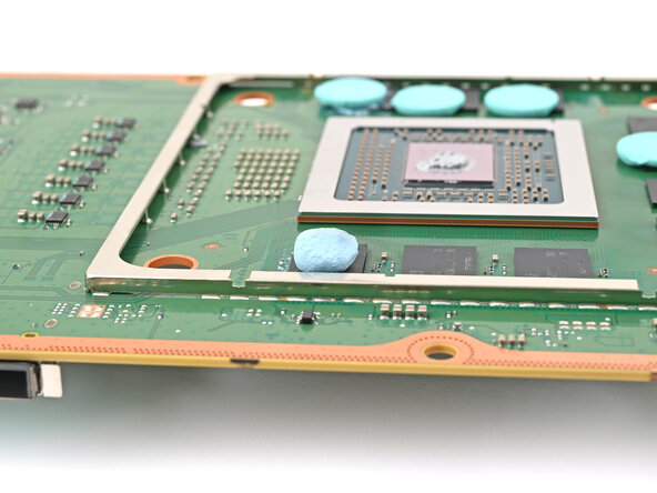
- Grab a small piece of thermal putty. Refer to the size of the thermal pad you're replacing for how much you need.
- Roll the thermal putty into a ball.
- Place the thermal putty where the damaged thermal pad was, making sure it's centered over the component—in this case a memory chip.
- Optionally, you can use the flat end of a spudger (or an included applicator) to spread the thermal putty over the surface of the component.
- When you reattach the heat sink, you'll compress the thermal putty and it'll spread the ball out.
- Apply a few drops of isopropyl alcohol (>90%) to the processor and use a coffee filter or a lint-free cloth to wipe away any residue.
- If you have to work near the small resistors, use cotton swabs instead.
- Repeat the previous step for the thermal paste on the heat sink.
- You can use a spudger to scrape off the thermal paste on the heat sink if it's too dried out.
- Apply a small bead of thermal paste to the center of the APU.
- Follow this guide in reverse order starting with this step to reattach the heat sink. Placing the heat sink back on the processor will evenly spread the thermal paste (and thermal putty if applicable) and bond both parts together.