Giiker Super Slide Teardown
ID: 182366
Description: The Giiker Super Slide is a game console based...
Steps:
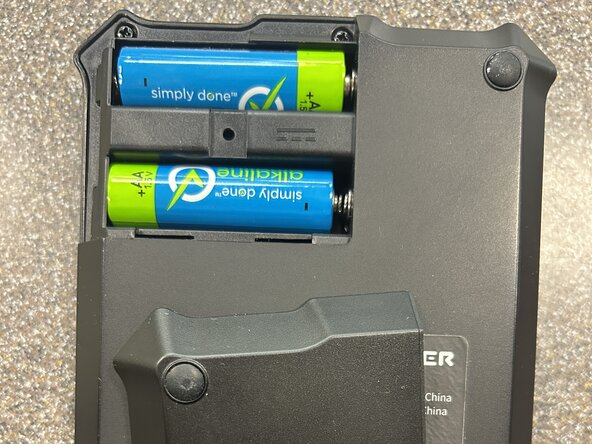
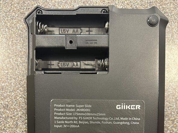
- Start by opening up the battery compartment and removing the two AAA batteries
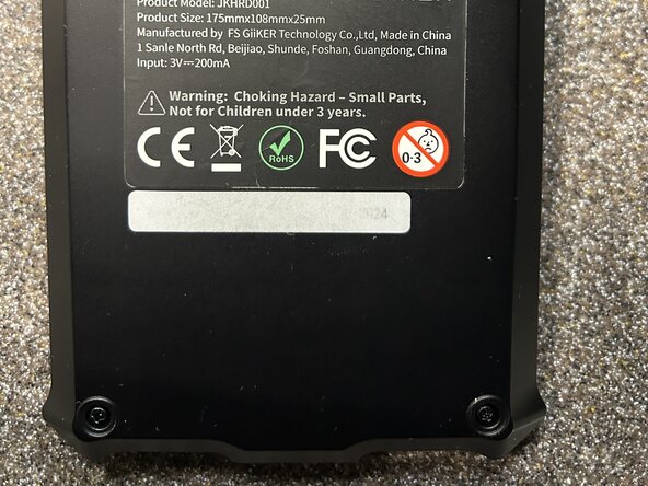
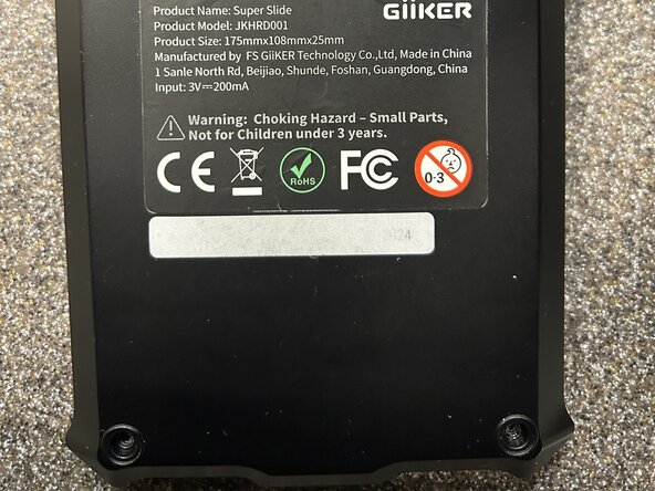
- Remove the two Phillips P1 screws
- Remove the two bottom feet by inserting your jimmy in the edge and prying up or prying with a fingernail
- Be careful not to scratch the adhesive under the feet unless you have adhesive to cut to shape
- Remove the next two Phillips P1 screws
- Remove the adhesive sticker (large) carefully from the back
- The sticker uses very strong adhesive. If you fail to get this off in one try, you will need isopropyl alchohol and an ifixit opening tool to scrape off the parts of the sticker penetrated by the alchohol
- Remove the last Phillips P1 screw holding down the back case
- Carefully lift up the back of the console
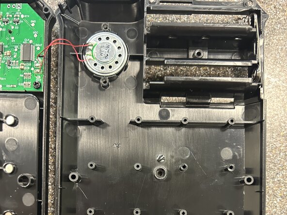
- Beware the two small wires connected to the back for the speakers
- Note that the inside magnets are not secured down, be very careful to not move the piece bay when removing the back unless you want to spend a lot of time putting them back in
- The top left corner of the back has some very light clips. Carefully twist side to side to get this open
- Remove all the magnets if desired
- To get the proper orientation of the magnets when reinserting, take a play piece and put the magnets on the piece back so they orient themselves. Using this orientation, insert them into the chassis and test with the back on that all are oriented correctly by putting the piece in play area. If they are not oriented right, the piece will not align
- Remove the two Phillips P1 screws holding down the speaker
- Carefully pull up the speaker out of its holder using one of the four notches to get a finger under and push or carefully prying with a spudger
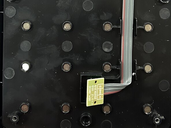
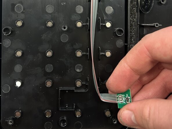
- Lift up the main piece hall effect sensor
- This does not adhere down well once removed, it is recommended to have some two sided tape to put under the sensor for reassembly
- Remove the two Phillips P1 screws holding down the action buttons
- Remove the Phillips P1 screws holding in the action buttons
- Remove the final two Phillips P1 screws holding down the main board
- Pull up the main board carefully and set to the side
- Pushing the screen in (from the viewing side) it can easily be removed. Pay note to the orientation in the image