Acer Aspire Go 15 AG15-31P-3947 Motherboard Replacement
ID: 185737
Description: If your motherboard is causing issues such as...
Steps:
- Before you begin, power off your device completely and disconnect from the charging adapter.
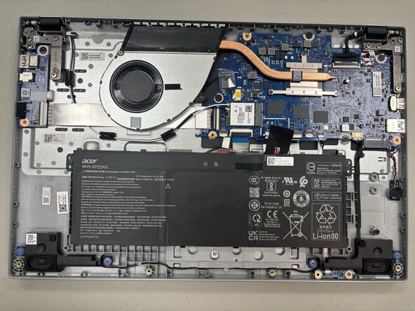
- Flip the laptop over so the bottom is facing up.
- Use a Phillips #1 screwdriver to remove ten 5.6 mm screws from the back panel.
- Place the end of an opening tool in the seam between the bottom and top case and slide it around the perimeter to release the clips holding it together.
- Use a few opening picks in the seam to keep the clips from reattaching.
- Remove the back panel.
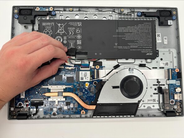
- Use the point of a spudger to push on alternating sides of the battery connector to "walk" it out of its socket on the motherboard.
- It may take a lot of alternating before the connector comes out. Be patient, and don't pull on the cables.
- To reconnect the cable, align the connector and use a spudger or clean fingernail to push it fully into the socket.
- Don't push on the cables themselves, or you may damage the connector.
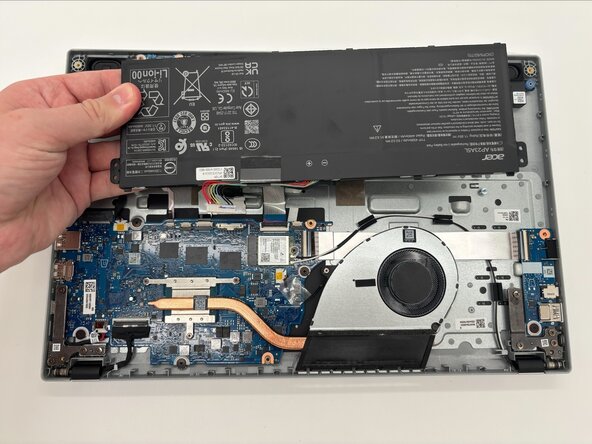
- Lift the battery upwards to remove it from the device.
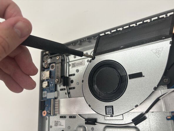
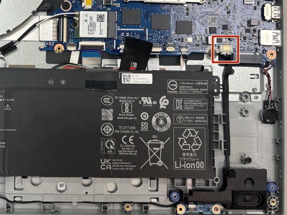
- Use the end of a spudger to push on alternating sides of the sliding connector and remove it from the socket on the motherboard.
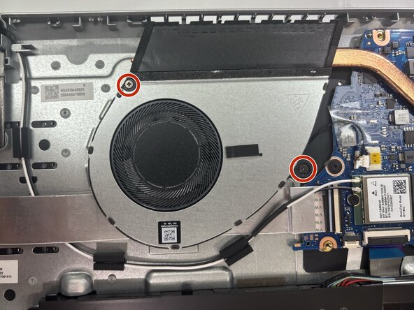
- Use a Phillips #1 screwdriver to remove the two 3 mm screws attaching the fan to the chassis.
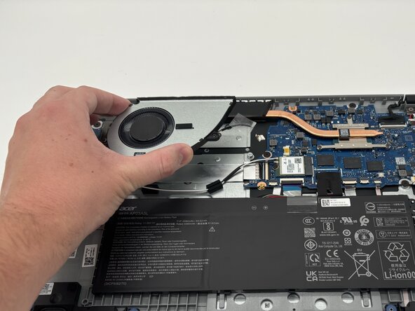
- Slide the fan out from the socket to remove it.
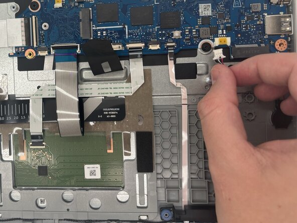
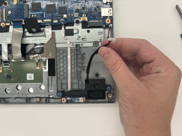
- To disconnect the speaker cable, use the point of a spudger to push on alternating sides of the connector to "walk" it out of its socket.
- Don't pull on the cables.
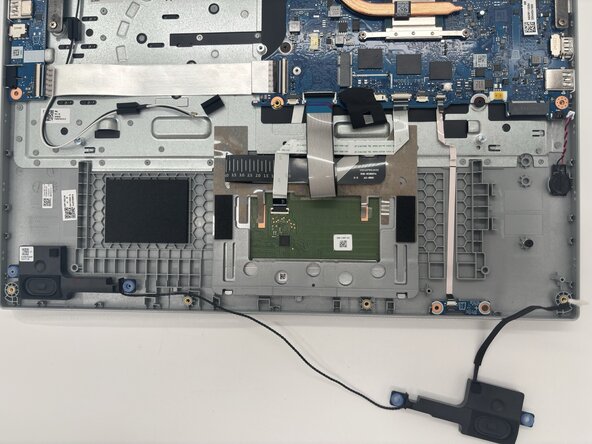
- Gently remove the speaker wire from routing guides.
- The wire may also be attached to the chassis with adhesive.
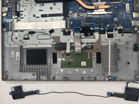
- Remove the speakers and wire that connects them from the laptop.
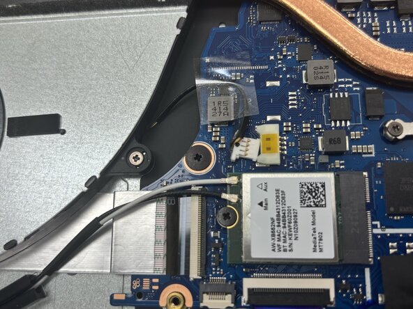
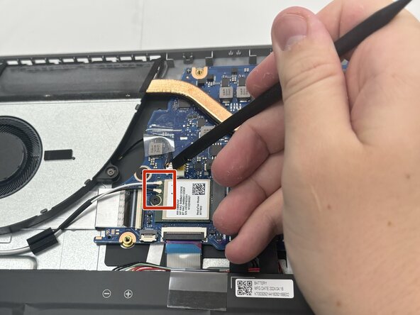
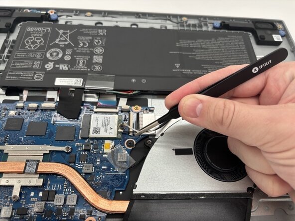
- Slide a thin, ESD-safe pry tool or angled tweezers under the metal neck of the white coaxial cable connector (as close to the head as possible) and lift straight up from the board.
- Repeat to disconnect the black coaxial cable connector.
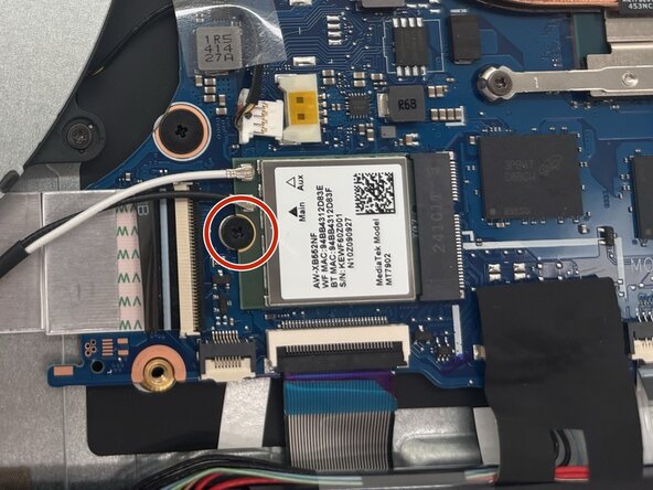
- Use a Phillips #1 screwdriver to remove the 2 mm screw securing the Wi-Fi card to the motherboard.
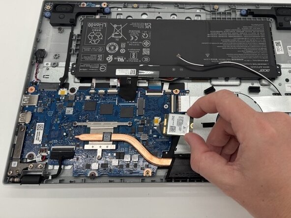
- Slide the Wi-Fi card out from the socket.
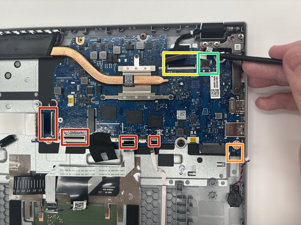
- Use a spudger or a clean fingernail to flip up the locking flap on the four ZIF connectors—this is the unlocked position.
- Use tweezers or your fingers to gently pull each cable out of its socket.
- Try pushing on alternating sides of the CMOS battery connector with a spudger to disconnect it from the socket.
- If that doesn't work, use a pair of tweezers to firmly grip the sides of the connector and pull straight away from the socket. Hold the tweezers closer to the connector to get a better grip.
- To disconnect the display connector, first, gently push the tip of a spudger under the metal buckle to unclip it, then swing it over the socket.
- Next, hold the buckle and cable together and gently pull the connector straight out of its socket.
- Use the point of a spudger to push on alternating sides of the power connector to "walk" it out of its socket.
- Don't pull on the wires or you risk damaging the connector and device.
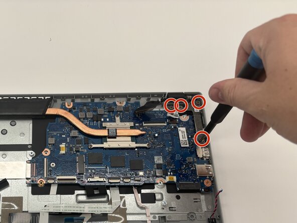
- Use a Phillips #1 screwdriver to remove the four screws from the hinge.
- Lift the hinge to allow the motherboard to be removed.
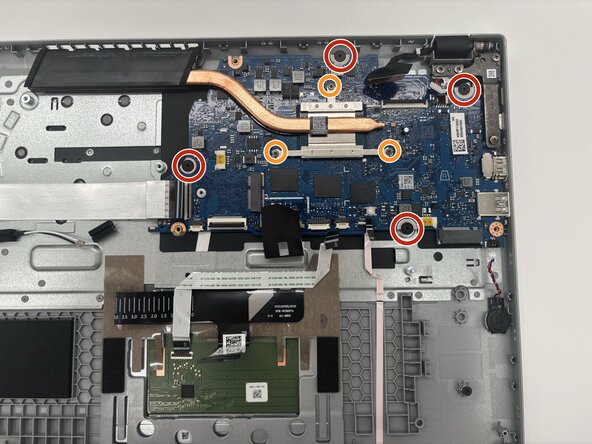
- Use a Phillips #1 screwdriver to remove the four screws securing the motherboard to the chassis.
- If your replacement board does not come with a heat sink, remove the three screws in descending order of the inscribed numbers on the heat sink.
- If you aren't replacing the heat sink, loosen the screws before removing the motherboard.
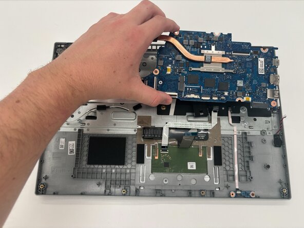
- Lift the motherboard from the laptop.