Framework Laptop 12 Display Replacement
ID: 186464
Description: Follow this guide to remove and replace the...
Steps:
- Before you begin repairs, unplug your laptop and shut it down from the operating system. This ensures that the laptop isn't in standby/suspend mode.
- The indicator LEDs along the edges should be unlit. The laptop should be silent.
- If you accidentally turn on the laptop during repair, hold the power button down for 10 seconds to shut it down.
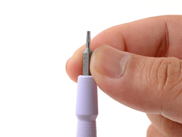
- Make sure your Framework Screwdriver has the T5 Torx bit (labeled as T-5) facing outwards. If it's not, pull the bit out and flip it.
- Open the laptop lid so that both the screen and the base lie flat on your work surface.
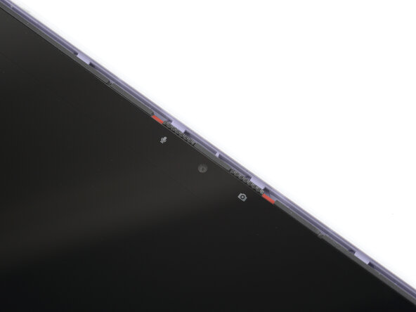
- The Display Cover is held in place with magnets along the top edge and clips along the remaining edges.
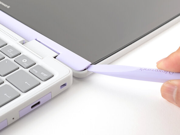
- Use the flat end of your Framework Screwdriver to pry up the right edge of the Display Cover.
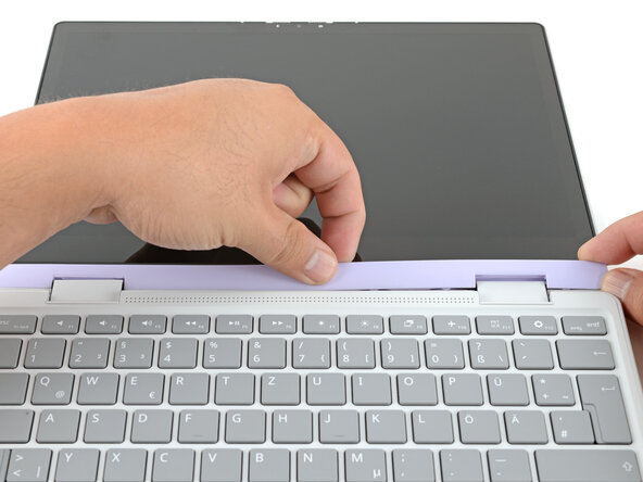
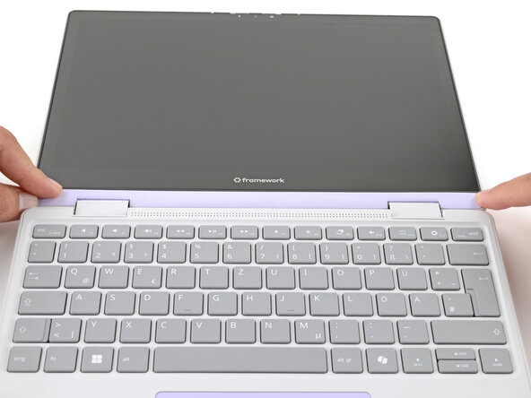
- Slide your fingers under the top edge of the Display Cover to release it from the laptop.
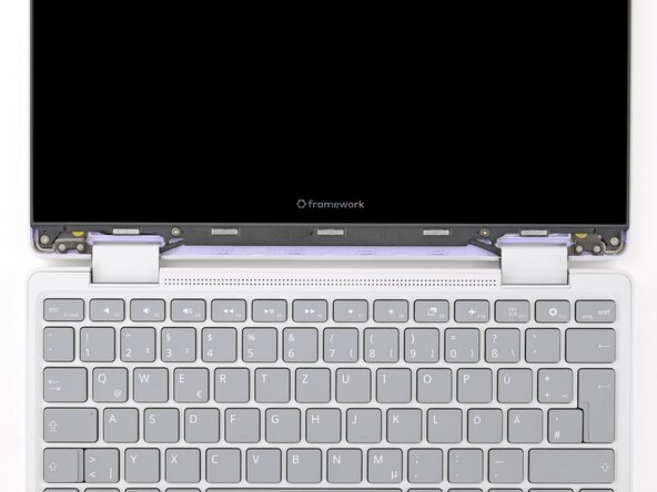
- Remove the Display Cover.
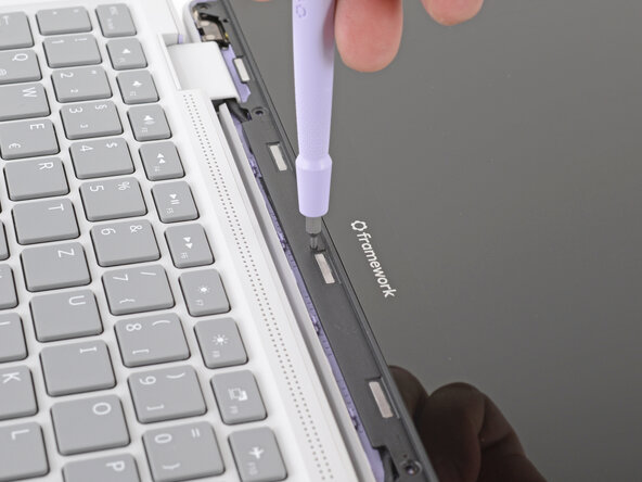
- Use your Framework Screwdriver to remove the four 3.3 mm‑long T5 Torx screws securing the display to the Top Cover.
- These screws are not captive. Store them in a safe location for reassembly.
- Insert the bit end of your Framework Screwdriver into the small hole on the display, below the Framework logo.
- Slide the display down towards the hinge edge to release the tabs holding the top edge of the display in place.
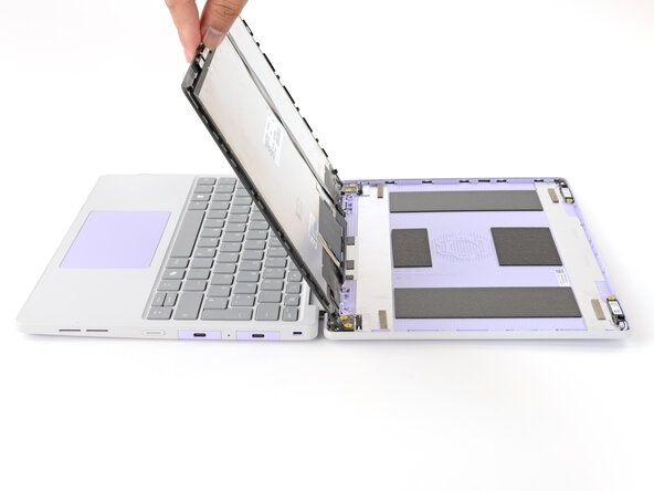
- Use your fingers to lift the top edge of the display from the Top Cover.
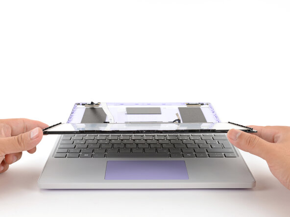
- Use your fingers to carefully swing the display over so it lies on top of the keyboard.
- Use your Framework Screwdriver to remove the two 3.3 mm‑long T5 Torx screws securing the webcam bracket on the top edge behind the display.
- These screws are not captive. Store them in a safe location for reassembly.
- Lift and remove the webcam bracket.
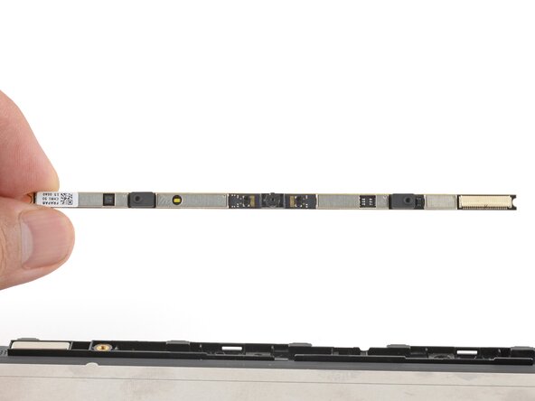
- Use the flat end of your Framework Screwdriver to lift the webcam out of its recess.
- Avoid touching the black camera module near the center of the webcam.
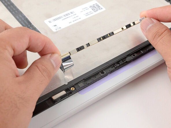
- Flip the webcam over and gently hold it down with your fingers.
- Use the flat end of your Framework Screwdriver or a fingernail to gently pry up the locking tab on the webcam cable ZIF connector.
- Slide the webcam cable out of its connector.
- Remove the webcam.
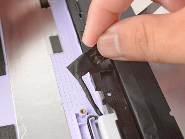
- The webcam cable is lightly adhered to the display.
- Grab the webcam cable with your fingers and slowly peel it away from the display.
- Carefully move the cable off of the display.
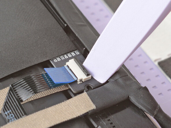
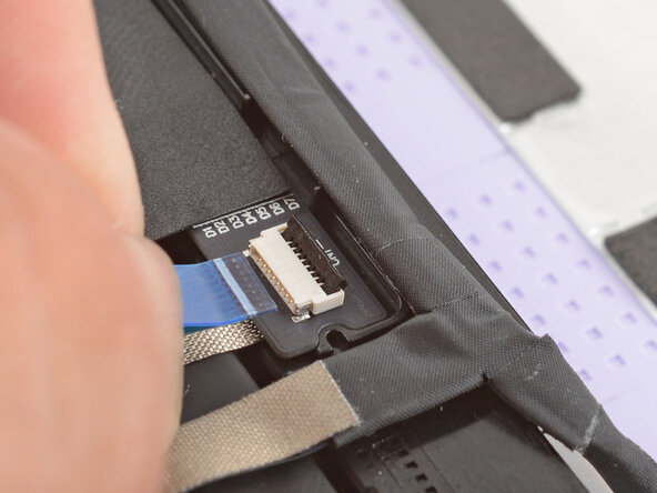
- Use the flat end of your Framework Screwdriver or a fingernail to gently pry up the locking tab on the touch control ZIF connector near the hinge edge of the display.
- Use your fingers to grab the touch control cable by the blue tab and slide the cable out of the connector.
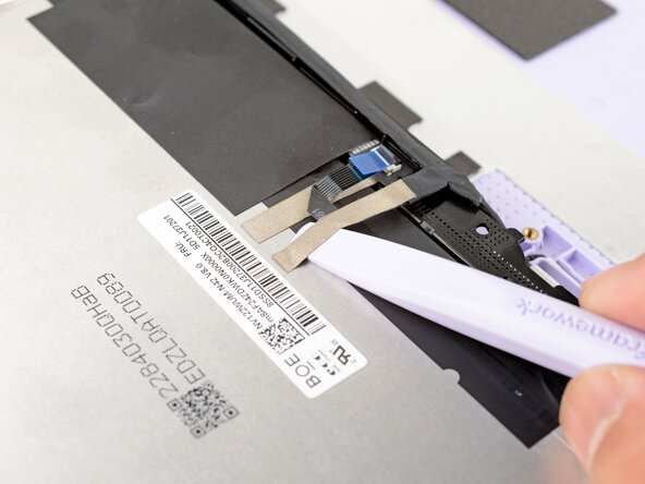
- Slide the flat end of your Framework Screwdriver under the grounding tape securing the display cable.
- Lift slowly to separate the tape from the display.
- Keep this tape clean and intact during your repair. You'll use it to attach the cable during reassembly.
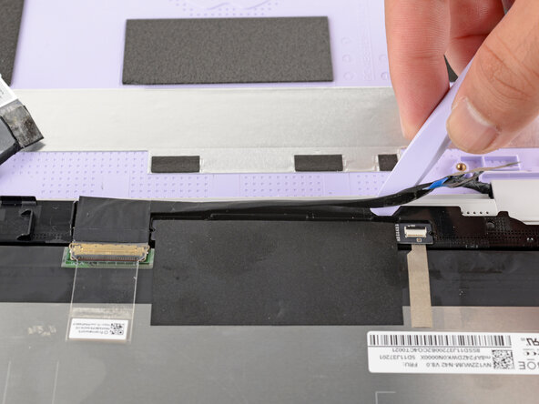
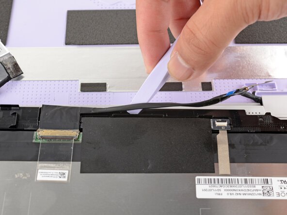
- The display cable is lightly adhered to the bottom edge of the display.
- Slide the flat end of your Framework Screwdriver under the length of the display cable to separate it from the display.
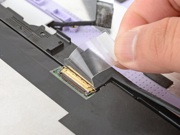
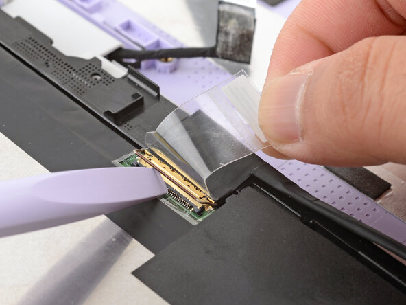
- Use your fingers to peel up the clear tab covering the display cable connector.
- Use the flat end of your Framework Screwdriver to flip up the locking bar around the display connector.
- Make sure the locking bar doesn't fall back in place while you disconnect the display cable.
- Grasp the display cable near the connector and slide it out of the connector.
- If you have trouble getting the cable to slide out, gently wiggle it to loosen the connection.
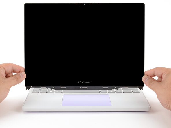
- Carefully lift and remove the display.
- Congratulations on completing disassembly! The remaining steps will show how to reassemble your Framework Laptop.
- The Framework Display Kit comes with an extra webcam bracket. If you're not using this kit to repair your display, skip this step.
- Inspect the replacement display and carefully peel off any protective liners.
- Use your Framework Screwdriver to remove the two 3.3 mm‑long T5 Torx screws securing the webcam bracket on the replacement display.
- Remove the webcam bracket.
- Remove any protective liners that may be in the webcam recess. The liners are normally clear or colored plastic films that easily detach.
- You can use the replacement bracket and screws, or you can reuse your existing ones.
- Carefully lay the display screen-side down on top of the Input Cover. The edge with the webcam should lay near the touchpad edge.
- The Input Cover magnets will align the display to itself.
- Use your fingers to slide the display off the Input Cover magnets towards the hinge edge so that the display cable can reach its connector.
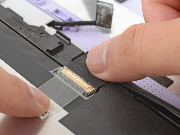
- Use your fingers to grab the display cable by the clear tab and the locking bar.
- Align the display cable with its connector and slide it in until it's fully seated.
- Swing the locking bar down over the connector.
- If the locking bar can't swing all the way down around the connector, you'll need to insert the cable deeper into the connector.
- Lay the clear tab over the connector and press it onto the display.
- Slide the touch control cable into the ZIF connector up to the printed line on the cable.
- Use your finger to flip down and gently press the locking tab in place.
- Use your finger to press the display cable grounding tape onto the metal back of the display.
- Use your fingers to press the display cable onto the display.
- Use your fingers to press the webcam cable onto the display.
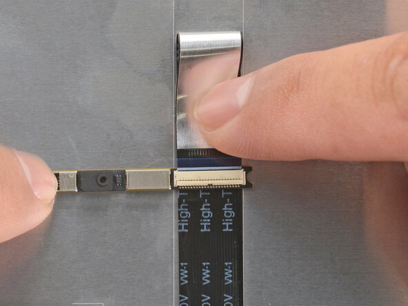
- Bend an inch (2.5 cm) of the webcam cable over so that the shiny side is facing you.
- Slide the webcam cable into the ZIF connector up to the printed line on the cable.
- Use your finger to flip down and gently press the locking tab in place.
- Use your fingers to flip the webcam back into its recess in the Top Cover.
- Align the webcam bracket to the Top Cover and lay it in place.
- Make sure the tabs on the top edge of the webcam bracket sit in their slots on the top edge of the display.
- Use your Framework Screwdriver to install the two 3.3 mm‑long T5 Torx screws to secure the webcam.
- Use your fingers to carefully swing the display over so it lies on top of the Top Cover.
- Align the display in the Top Cover such that the top edge of the display is slightly below the top edge of the Top Cover.
- Use your fingers to slide the display upwards to latch the tabs on the top edge of the display.
- The top edge shouldn't have any gaps when the display's in place.
- Use your Framework Screwdriver to install the four 3.3 mm‑long T5 Torx screws to secure the display to the Top Cover.
- Tighten the screws until they're snug. Don't over-tighten them, or you may damage the screw tabs.
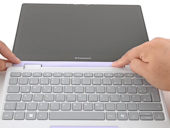
- Align the Display Cover to the bottom of the display.
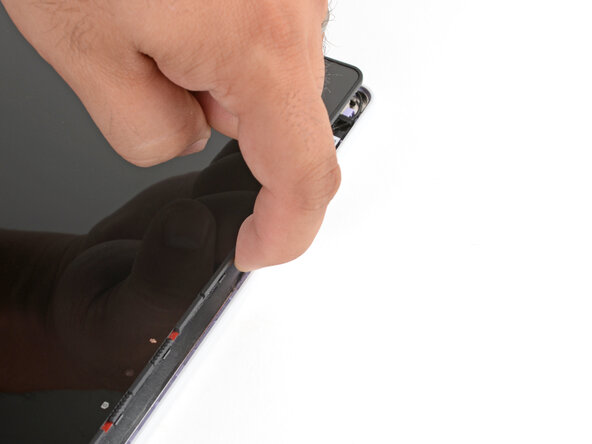
- Use your finger to press along the length of the Display Cover to snap it onto the laptop.
- Make sure all the clips along the left, top, and right edges are fully seated.