GameSir Nova 2 Lite Button Replacement
ID: 199163
Description: If the buttons on your GameSir Nova 2 Lite...
Steps:
- Before you take your controller apart make sure it is powered off by holding the power button down for 15 seconds until it stops blinking.
- Use a Phillips #0 screwdriver to remove the four 8.5 mm screws from the bottom of the controller's casing.
- Insert an opening tool between the two halves to open the controller's casing.
- You will feel several internal latches called “snap-fit connectors.”
- Disconnect them by sliding the opening tool along the seam in the casing, applying continuous pressure.
- Once you find a connector, apply increased pressure until you hear a snapping sound.
- Repeat this process until all of the connectors are disconnected.
- Separate the top and bottom of the controller case.
- Set aside the bottom half of the shell.
- Position the controller so that the motherboard is visible.
- Use the point of a spudger to push on alternating sides of the battery connector to "walk" it out of its socket.
- If that doesn't work, use a pair of tweezers to firmly grip the sides of the connector and pull straight away from the socket. Hold the tweezers closer to the connector to get a better grip.
- If the battery appears swollen follow this link.
- The battery is held in place by double-sided adhesive.
- Use a spudger to loosen the tape securing the battery.
- Remove the battery from the controller.
- Push on alternating sides of the JST connector to release it from the socket on the circuit board.
- If that doesn't work, use a pair of tweezers to firmly grip the sides of the connector and pull straight away from the socket. Hold the tweezers closer to the connector to get a better grip.
- Pull the motor out of its socket.
- Repeat the steps for the other rumble motor.
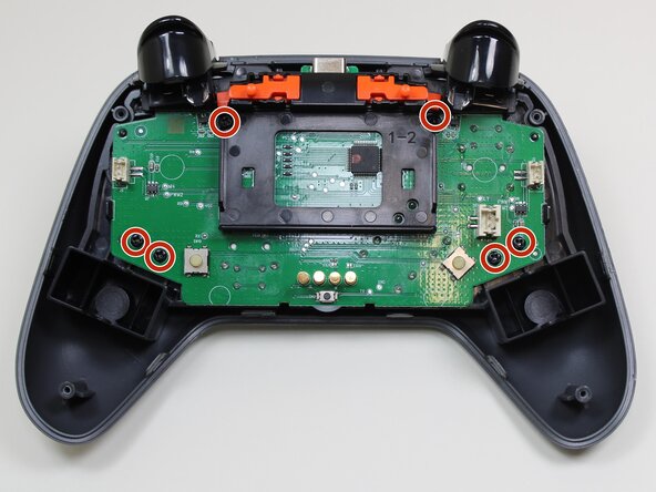
- Use a Phillips #0 screwdriver to remove the six 5.7 mm screws securing the motherboard.
- Separate the midframe that holds the motherboard from the outer shell.
- At this point the only thing holding the buttons in place is gravity.
- Remove the buttons from the top case.