Microsoft Surface Pro 8 Fan and Heat Sink Assembly Replacement
ID: 212662
Description: Follow this guide to replace the fan and heat...
Steps:
- Before starting this repair, allow your Surface Pro's battery to drain below 25%. A charged battery may catch fire if damaged.
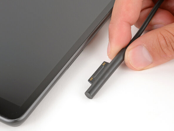
- Unplug all cables and fully shut down your tablet.
- If you have a keyboard attached, remove it.
- Open the kickstand to about 90 degrees.
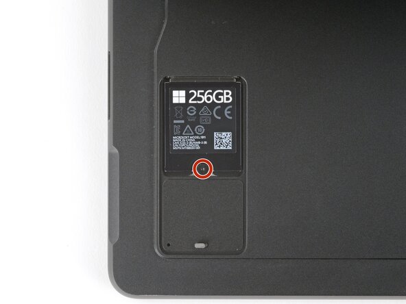
- Firmly press a SIM eject tool into the small hole in the corner of the SSD door until it pops up.
- Alternatively, you can also use a small, straightened paper clip.
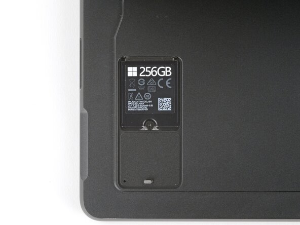
- Remove the SSD door.
- Removing the SSD also functions as a battery disconnect and should be done before all major repairs.
- Use a Torx Plus 3IP screwdriver to remove the 2.3 mm‑long screw securing the SSD.
- Don't pull up at a sharp angle, or you may damage the SSD and its socket.
- Use your fingers to pull the SSD out of its socket at a shallow angle.
- If you're having trouble gripping the SSD, use a spudger or your fingernail to lift it slightly.
- Leave the SSD removed to keep the battery disconnected.
- Slide the SSD door back into its recess and press down on the bottom edge until it clicks into place.
- Close the kickstand and flip your device over so the screen is facing up.
- Don't insert your pick more than 8 mm when separating the screen adhesive. Otherwise, you may damage your device's internals.
- When separating the top edge adhesive, follow instructions carefully to avoid damaging the front camera.
- To prevent inserting your pick too far, measure 8 mm from the tip and mark the opening pick with a permanent marker.
- Alternatively, tape a coin to a pick 8 mm from the tip.
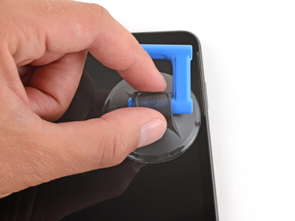
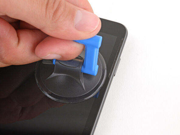
- Apply a suction handle to the top right corner of the screen, near the bottom of the speaker cutout.
- Pull up on the suction handle with strong, steady force until a gap forms between the screen and frame.
- If you're having trouble, try using an iOpener to heat the screen.
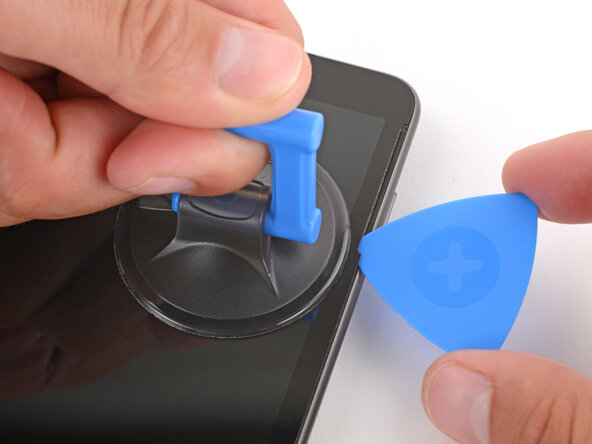
- Insert the tip of an opening pick in the gap you just created.
- Depending on the age of your device and condition of the screen adhesive, you may need to use an iOpener to heat the screen if you're having trouble separating the adhesive.
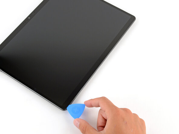
- Slide the opening pick down the right edge and around the bottom right corner to separate the adhesive.
- Slide the opening pick along the bottom edge and around the bottom left corner to separate the adhesive.
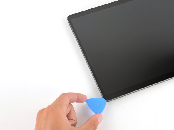
- Slide the opening pick up the left edge to separate the adhesive.
- You may need to use a suction handle to help separate the adhesive near the left speaker cutout.
- Don't slide the pick over the front facing camera. Remove the pick enough so that it can slide past the camera without touching it.
- Slide the opening pick along the top edge to separate the adhesive.
- You'll likely need to slide the pick around the perimeter a second time to fully separate all the screen adhesive.
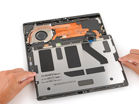
- Once the screen is fully separated, slightly lift the top edge and flip the screen so it can lay flat.
- Be careful not to strain the screen cables.
- During reassembly:
- Remove all the remaining adhesive liners, carefully holding the screen above your device as necessary.
- Flip the screen over and align the bottom edge, using the frame's lip to properly orient it.
- Once the bottom edge is properly aligned, lay the screen onto the frame.
- Use your fingers to press down on the entire perimeter of the screen to secure it in the frame.
- Optionally, you can lay the device screen side down on a clean surface and stack 4–5 heavy books squarely on top of your device. Leave the books in place for at least thirty minutes. The lighter the books, the longer they should be left. Ideally, leave them stacked overnight.
- Use an arm of your tweezers to pry up and unclip the corners of the screen cable cover (on the screen itself, not in the device).
- Be careful not to deform the shield too much, as you'll need to reinstall it during reassembly.
- Remove the cover.
- Use a spudger to pry up and disconnect the screen cable press connector.
- Remove the screen.
- During reassembly:
- Use a spudger and tweezers to scrape up and remove all the old screen adhesive from the frame. Clean up any residue with high-concentration (>90%) isopropyl alcohol and a coffee filter or lint-free cloth.
- If you're reusing your screen, repeat the process to remove any adhesive and its residue from the underside of the screen.
- To prevent damaging your screen, press gently and make sure nothing is under the screen while you work.
- Before applying any screen adhesives, find their proper orientation on the frame. Use cutouts and notches in the adhesive to match each strip to its spot on the perimeter.
- Carefully align and apply the adhesive strips to the frame—don't remove the remaining top liners on the strips.
- Lay the screen upside down on the frame so you can reconnect its cable. The screen should be oriented so when you flip it over, the top edge of the screen is lined up with the top edge of the frame.
- Before starting your repair, unplug all cables and fully shut down your Surface Pro.
- There are two models of the Surface Pro 8—LTE (model 1982) and Wi‑Fi (model 1983). The photos in this guide are from model 1983. If you have a model 1982, there may be slight visual discrepancies, but the procedure will still work. The fan connector position will be slightly different.
- Use a spudger to lift the small, hinged locking flap on the fan's ZIF connector.
- Grip the fan cable's plastic pull tab with tweezers and slide the cable fully out of its socket.
- If you have a model 1982 Surface Pro, skip this step.
- Slide the tip of a spudger under the tape on the top edge of the fan and lift to remove it.
- Make sure you're only lifting the tape and not the twisted speaker cable underneath.
- During reassembly:
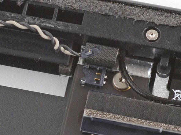
- Check if the speaker wire got disconnected near the top edge of the fan.
- If it did, align the connector over its socket and push down with the flat end of a spudger to reconnect it—the connector should click into place.
- If you have a model 1982 Surface Pro, the screw locations will be slightly different.
- Use a Torx Plus 3IP screwdriver to remove the 12 screws securing the fan and heat sink assembly:
- Three 3.2 mm‑long light gray screws
- One 2.0 mm‑long dark gray screw
- Four 2.5 mm‑long silver screws
- Four 2.5 mm‑long silver, CPU tensions screws securing the heatsink
- During reassembly, install these screws first. Tighten them a few turns at a time in an X pattern. For example: top left, bottom right, top right, bottom left.
- Be careful during this step, as the heatsink can easily bend out of shape. Don't pry against the copper heat pipes.
- Use a spudger to gently pry up on the heatsink along the top and bottom edges.
- Thermal paste bonds the heat sink to the CPU. Depending on the age of your device and condition of the thermal paste, the heat sink may not separate immediately—try wiggling it to help.
- Use two hands to grip the fan and heatsink assembly close to the center and lift to remove it.
- Use your fingers to gently remove the metal heat sink gasket and set it aside.
- The gasket will either be on the motherboard or on the bottom of the heat sink.
- During reassembly, follow this step to replace the thermal paste and pads.
- Your device has thermal paste that needs to be replaced, as well as two thermal pads that need to be checked. They will either be on the device or their corresponding spots on the bottom of the heat sink.
- Follow this guide to clean the processor and thermal module and apply thermal paste.
- Make sure you apply thermal paste to both processor dies.
- Check the condition of the two thermal pads—one is just to the left of the CPU and the other is in the bottom right corner of the device.
- If the thermal pads are damaged:
- Use a spudger to scrape up and remove the damaged pad(s). Clean up any residue with high-concentration (>90%) isopropyl alcohol and a coffee filter or lint-free cloth.
- Cut the replacement thermal pads to size and put them in place.