Altyk Le petit PC portable L14 Palmrest and Keyboard Replacement
ID: 219144
Description: Replacing the palmrest and keyboard on an Altyk...
Steps:
- Turn your machine over so that the bottom is facing you.
- You have 10 screws facing you:
- 8 identical short Phillips screws (PH000)
- 2 identical long Phillips screws (PH000) in the corners near the clutch hinges
- Once the screws are removed, you can pry up with an opening pick as shown in the second photo. There is no risk of breaking any snap fits; there are none.
- Locate the battery connector.
- There are two ways to remove the battery:
- Either use plastic or ceramic tweezers to separate the connector from the motherboard by using the corners of the connector as indicated in red.
- Grasp the battery wires shown in blue and pull gently toward you to disconnect the battery.
- Identify and remove the 6 screws marked on the diagram
- Remove the tape securing the cables under the battery and the BIOS battery.
- Your battery is free and ready to be removed.
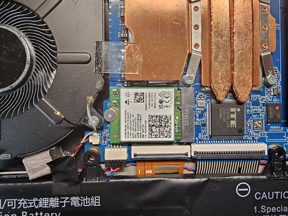
- Remove the first ribbon cable by lifting the connector; you can then pull the ribbon cable out. Feel free to push it back slightly to free up workspace.
- Remove the second ribbon cable and do the same as you did for the first: push it back for the following steps.
- Remove the three screws securing the board.
- Once the two screws are removed, the Ethernet connector's snap fit is simply resting on the motherboard. Be careful not to lose it!
- Remove the snap fit securing the Ethernet connector (placed on the daughterboard, now free of its two screws) and you can now remove the latter by prying from the cooling fan side. To install the new one, follow this guide in reverse.
- Remove the 4 processor heatsink screws and lift it off as shown in the second photo
- Remove the tape covering the display connector.
- You can then open the connector and free the display cable. Feel free to move it slightly backward to clear your workspace.
- Peel back the tape securing the Wi-Fi antennas
- Disconnect the Wi-Fi antennas
- Disconnect the 7 different connectors/cables attached to the motherboard
- Remove all the screws securing the motherboard.
- Once the 5 screws are removed, you can lift the motherboard from the left and remove it. Install the new one the same way and follow this guide in reverse order to reassemble your machine.
- The first thing to do is to disconnect the speakers
- Remove the black protective tape from the speaker cables to separate it from the keyboard backlight (as shown in image 2)
- Using tweezers or any other tool suitable for prying (ensure it is sturdy, as the adhesive is quite rigid), gradually pry up the right and left speakers.
- Simply pull on the cable to bring it toward you. The speakers are now free, and you can simply reassemble everything in reverse order to finish.
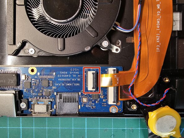
- Remove the two orange ribbon cables connecting the motherboard to the daughterboard
- Remove the two white ribbon cables connecting the touchpad to the motherboard
- Lift the cable out of its notch to free it, as shown in the second photo.
- Open the display to 90° before working on the clutch hinges (this will allow you to remove the display more easily)
- Remove the three screws on the left side and right side; however, to prevent everything from falling at once, place a hand between the display and the keyboard to remove the last screws
- Detach the two insulating strips and fold them back as shown in the second photo
- To unstick the touchpad from the palm rest, you need to dissolve the double-sided tape; don't hesitate to add a solvent (I personally use Essence F).
- Once the adhesive remover has taken effect, you can use the opening picks and insert them on both sides of the touchpad as shown in the first two photos.
- Once both pads are detached, the touchpad will come out through the front of the PC as shown in the third photo. You can now use your new palmrest with keyboard and follow the steps of the guide in reverse order to reassemble the device.