iPhone 5c Audio Control and Power Button Cable Replacement
ID: 23004
Description: Use this guide to replace the upper component...
Steps:
- If your display glass is cracked, keep further breakage contained and prevent bodily harm during your repair by taping the glass.
- Lay overlapping strips of clear packing tape over the iPhone's display until the whole face is covered.
- This will keep glass shards contained and provide structural integrity when prying and lifting the display.
- Wear safety glasses to protect your eyes from any glass shaken free during the repair.
- Before you proceed, discharge your iPhone battery below 25%. A charged lithium-ion battery can catch fire and/or explode if accidentally punctured.
- Power off your iPhone before beginning disassembly.
- Remove the two 3.8 mm P2 Pentalobe screws on either side of the Lightning connector.
- The next two steps demonstrate using the iSclack, a great tool for safely opening the iPhone 5c that we recommend for anyone doing more than one repair on an iPhone 5, 5s, or 5c. If you aren't using the iSclack, skip to Step 5.
- Close the handle on the iSclack, opening the suction-cup jaws.
- Place the bottom of your iPhone in between the suction cups, against the plastic depth gauge.
- The top suction cup should rest just above the home button.
- Open the handles to close the jaws of the iSclack. Center the suction cups and press them firmly onto the top and bottom of the iPhone.
- Hold onto your iPhone securely and close the handle of the iSclack to separate the suction cups, pulling the front panel up from the rear case.
- The iSclack is designed to safely open your iPhone just enough to separate the pieces, but not enough to damage any cables.
- Peel the two suction cups off your iPhone.
- Skip the next three steps and continue on to Step 8.
- Press a suction cup onto the screen, just above the home button.
- Be sure the cup is completely on the screen to get a tight seal.
- Make sure the suction cup is firmly attached to the front panel assembly.
- While holding the iPhone down with one hand, pull up on the suction cup to slightly separate the front panel assembly from the rear case.
- Take your time and apply firm, constant force. The display assembly is a much tighter fit than most devices.
- With a plastic opening tool, begin to gently pry the rear case down, away from the display assembly, while you pull up with the suction cup.
- There are several clips attaching the front panel assembly to the rear case, so you may need to use a combination of the suction cup and plastic opening tool to free the front panel assembly.
- Pull the plastic nub to release the vacuum seal on the suction cup.
- Remove the suction cup from the display assembly.
- Lift the home button end of the front panel up to gain access to the connectors near the top of the phone.
- Open the display to about a 90º angle, and lean it against something to keep it propped up while you're working on the phone.
- In a pinch, you can use an unopened canned beverage to hold the display.
- Add a rubber band to keep the display securely in place while you work. This prevents undue strain on the display cables.
- Remove the two 1.6 mm Phillips #000 screws securing the metal battery connector bracket to the logic board.
- Remove the metal battery connector bracket from the iPhone.
- Use a spudger or a clean fingernail to gently pry the battery connector up from its socket on the logic board.
- Be very careful to only pry up on the battery connector itself and not the socket on the logic board. If you pry up on the logic board socket or the board itself, you may destroy the socket or damage nearby components on the board.
- Remove the following Phillips #000 screws securing the front panel assembly cable bracket to the logic board:
- Two 1.3 mm screws
- One 1.7 mm screw
- One 3.25 mm screw
- It is especially important to keep track of your screws in this step for reassembly. Accidentally using the 3.25 mm screw or the 1.7 mm screw in the bottom right hole will result in significant damage to the logic board causing the phone to no longer boot properly.
- Be careful not to over-tighten the screws. If they don't fit easily when you are securing them, they may be the wrong size—don't force them.
- Remove the front panel assembly cable bracket from the logic board.
- Use a plastic opening tool or a fingernail to disconnect the front-facing camera and sensor cable connector.
- Be sure to only pry up on the connector, and not on the socket on the logic board.
- Make sure the battery is disconnected before you disconnect or reconnect the cables in this step.
- Use a plastic opening tool or a fingernail to disconnect the LCD cable connector.
- The LCD and Digitizer connectors are on the same cable assembly, so prying the LCD connector up should disconnect both connectors. Double check that the two cables are fully disconnected before removing the display.
- When reassembling your phone, the LCD cable may pop off its connector. A blank screen, or white lines on the display could be caused by a loose connection. Should this happen, reconnect the cable and power cycle your phone. The best way to power cycle your phone is to disconnect and reconnect the battery.
- Remove the front panel assembly from the rear case.
- Shut your phone down completely before removing the SIM card and tray.
- Insert a SIM card eject tool or a paperclip into the small hole in the SIM card tray.
- Press the SIM card eject tool inwards to eject the tray.
- This may require a significant amount of force.
- Remove the SIM Card tray assembly from the iPhone.
- During reassembly, ensure that the SIM card is in the proper orientation relative to the tray.
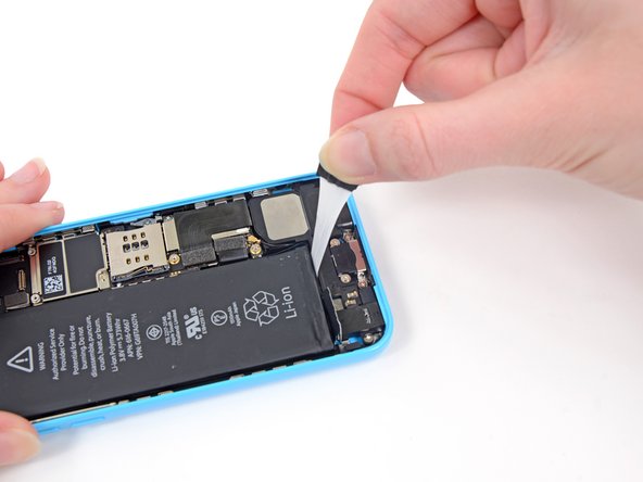
- Run the tip of a spudger between the battery and the headphone jack to unfold the battery adhesive tab.
- Pull the battery adhesive tab away from the phone.
- Cut the black battery adhesive tab between the two white adhesive strips, separating them.
- Try to keep the strips flat and unwrinkled during this procedure; wrinkled strips will stick together and break instead of pulling out cleanly.
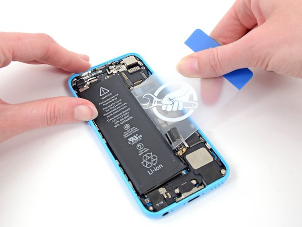
- Slowly pull one of the battery adhesive strips away from the battery, toward the bottom of the iPhone.
- Pull steadily, maintaining constant tension on the strip as it slips out from between the battery and the rear case. For best results, pull the strip at a 60º angle or less.
- Guide the strip carefully around the corner and up the side of the battery. Be careful not to snag it on any of the other internal iPhone components.
- The strip will stretch to many times its original length. Continue pulling, re-grabbing the strip near the battery if necessary, until the entire strip comes free.
- Repeat to remove the second strip.
- Remove the battery from your iPhone.
- If one, or both, of the adhesive strips tears, and you are unable to retrieve it with a set of tweezers, do not pry the battery out of the phone. Continue on to the next steps to safely remove your battery.
- Apply a few drops of isopropyl alcohol (90% or greater) under the battery and let it flow around the adhesive to help weaken it. High concentration isopropyl alcohol acts as a solvent and dries without leaving any residue, so it will not hurt your iPhone.
- Carefully wedge a plastic card under the battery on the side nearest the logic board.
- Do not pry against the logic board or you may damage the phone.
- Avoid prying near the top edge of the battery, or you may damage the upper component ribbon cable.
- Slide the card from the top of the battery to the bottom, pushing toward the edge of the case.
- If necessary, repeat the same procedure with the case side of the battery.
- If the battery is still stuck to the case, follow our iOpener heating instructions or use a hair dryer to heat the adhesive securing your battery to the rear case.
- Lay the iOpener flat on the backside of the iPhone to the right of the camera. Smooth it out so that there is good contact between the back of the iPhone and the iOpener.
- Let the bag sit on the iPhone for approximately 90 seconds before attempting to remove the battery.
- If using a hair dryer or heat gun, heat the back of the iPhone until it's slightly too hot to touch.
- Do not apply heat directly to the battery.
- Overheating the iPhone may ignite the battery.
- Lift and remove the battery from the iPhone.
- If there's any alcohol solution remaining in the phone, carefully wipe it off or allow it to air dry before installing your new battery.
- There should be no resistance. If the battery remains stuck, reheat the iOpener and pry again.
- If your replacement battery came in a plastic sleeve, remove it before installation by pulling it away from the the ribbon cable.
- Before you adhere the replacement battery, temporarily reconnect the battery connector to the motherboard socket. This ensures that the battery is properly aligned in its recess.
- Adhere the battery, disconnect it, and continue reassembling your device.
- If your new battery doesn’t have adhesive preinstalled, refer to this guide to replace the adhesive strips.
- Perform a hard reset after reassembly. This can prevent several issues and simplify troubleshooting.
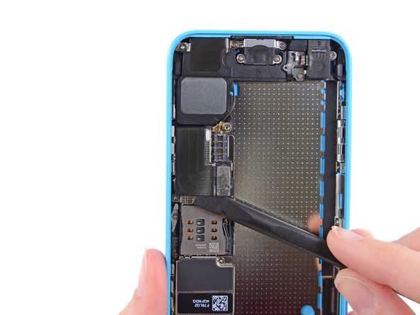
- Use a spudger to disconnect the Lightning connector ribbon cable from its socket on the logic board.
- The Lightning connector cable is lightly adhered to a shield on the logic board. Use the flat end of a spudger to gently peel the cable up.
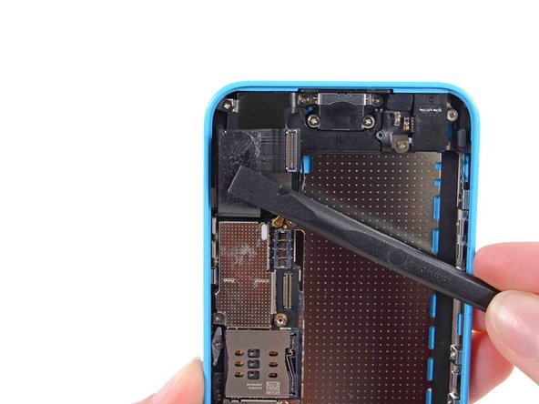
- Flip the Lightning connector cable up out of the way of the logic board.
- Disconnect the lower antenna connector from the base of the logic board.
- Use the flat end of a spudger to disconnect the audio control cable connector from its socket on the logic board.
- Disconnect the rear-facing camera cable connector from its socket on the logic board.
- A small piece of tape may obscure the logic board grounding clip. If so, use a pair of tweezers to remove the tape.
- Remove the following screws securing the logic board grounding clip to the rear case:
- 1.2 mm Phillips #000 in the top side-wall
- 2.5 mm Phillips #000
- Use tweezers to remove the logic board grounding clip.
- Remove the following screws securing the logic board to the rear case:
- Two 2.3 mm Phillips screws
- Three 2.7 mm standoff screws
- Standoff screws are best removed with a standoff screwdriver or standoff driver bit. A small flathead screwdriver can also do the job—but use extra caution to ensure it doesn't slip and damage surrounding components.
- Holding the phone level, lift the bottom end of the logic board up enough to grasp it with your fingers.
- Pull the logic board away from the rear-facing camera just enough to expose the gold contact cap under the top end of the board.
- Remove the gold-colored contact cap from the threaded post in the rear case, and set it aside.
- Flip the logic board up toward the volume control buttons to expose the antenna connector.
- Do not try to remove the logic board from the rear case yet, as it is still connected by an antenna cable on the back.
- Disconnect the antenna connector from the back of the logic board.
- Remove the logic board from the rear case.
- Remove the two 1.5 mm Phillips #000 screws securing the rear camera cover to the rear case.
- Remove the rear facing camera cover.
- Remove the rear facing camera.
- Remove the following screws securing the vibrator motor to the rear case:
- 1.2 mm Phillips #000
- 2.2 mm Phillips #000
- Remove the vibrator motor.
- Remove the following screws securing the upper assembly contact bracket to the rear case:
- 3.0 mm standoff screw
- 1.5 mm Phillips #000 screw
- Remove the upper assembly contact bracket from the rear case.
- A small rubber bumper may fall off the top of the bracket—take care not to lose it.
- Remove any foam tape obscuring the screws near the camera cavity.
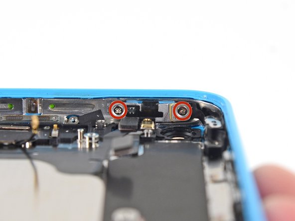
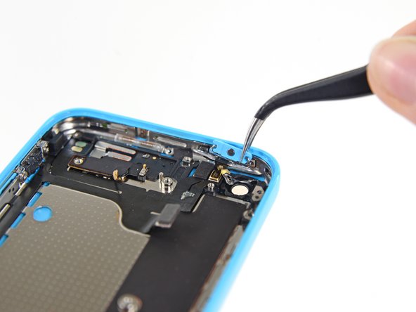
- Remove the two 1.4 mm Phillips #000 screws securing the power/sleep button bracket.
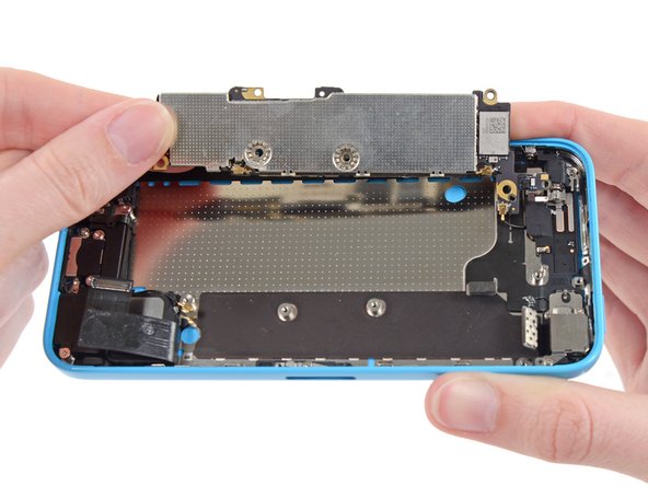
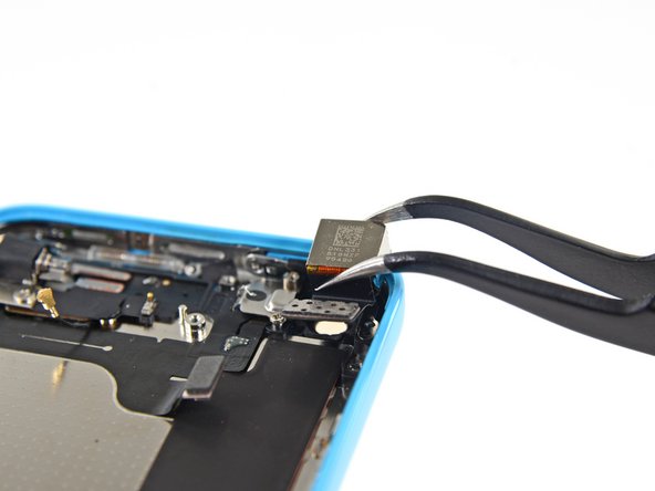
- Use the pointed end of a spudger to gently fold the power/sleep button bracket down from the top of the rear case.
- Use tweezers to grab and remove the button.
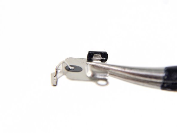
- For reassembly, note the orientation—the metal bar should be flush with the bottom of the button.
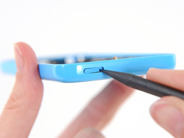
- If you can't get a hold on the power button from inside the case, use a spudger to slightly push it in from the outside.
- Remove the two 1.6 mm Phillips #000 screws from the mute/silent switch bracket.
- Remove this mute/silent switch bracket clip and set it aside.
- During reassembly, the bracket clip goes over the mute/silent switch bracket. Ensure the angled portion is to the right.
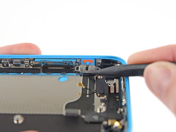
- Use the tip of a spudger to flip the mute/silent switch bracket down.
- Use tweezers to remove the mute/silent switch.
- Note the orientation for reassembly: The red line should be at the top of the button. The notch in the back of the switch should be in the same position as, and mate with, the mechanical switch on the cable.
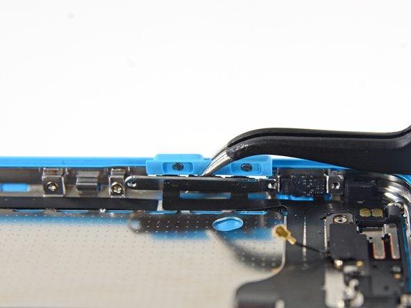
- Remove the 1.6 mm Phillips #000 screw securing the volume rocker bracket to the side wall.
- Use the tip of a spudger to fold the volume rocker bracket down from the side wall. Remove the volume rocker.
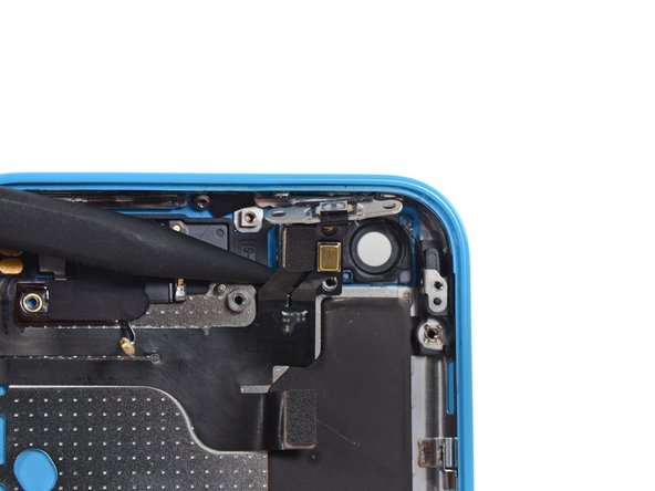
- Use the tip of a spudger to peel the power/sleep button cable off of the rear case.
- Run a spudger gently under the flash assembly cable to separate it from the phone.
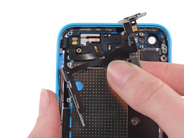
- Peel the upper assembly cable up from right to left to separate the adhesive holding it to the case.
- Take extra care in peeling the vibrator contact end of the cable off of the phone.
- Do not touch the contacts; finger oils can corrode the metal and prevent a solid connection.
- You can now remove the assembly from the phone.