Canon PowerShot ELPH 300HS Lens Zoom Unit Replacement
ID: 23369
Description: Before you get started, make sure you are worki...
Steps:
- Before you begin taking apart your device, the first, and MOST IMPORTANT STEPS are to:
- Turn off your camera.
- Remove the battery to prevent risk of shock.
- Turn off your camera by pressing the power button, located on the top-center of the device.
- Locate the battery door on the bottom right area of the camera case.
- Place your finger firmly on the black rubber pad on the battery door and slide the door to the right to open it.
- Locate the orange battery release button beneath the battery door.
- Slide the battery release button downward to release the battery.
- Be careful when removing screws, as they are stripped easily.
- Remove the two screws located on the left side of the camera case, using the Phillips screwdriver #00 (2.0 mm).
- Remove the two screws on the bottom of the camera located near the battery door (Phillips #00 screwdriver) (4.0 mm).
- Remove the screw located on the lower right side of the camera case (Phillips #00 screwdriver) (4.0 mm).
- Remove the HDMI A/V out port cover located on the upper right side of the camera.
- Remove the screw located just beneath the port cover removed in step 2. (Phillips #00 screwdriver) (2.0 mm).
- Remove the back portion of the camera case to reveal the screw located on the top of the case.
- Remove the screw from the top of camera case, located next to the shutter button (Phillips #00 screwdriver) (1.5 mm).
- Carefully pry the case apart at the seem, using your fingers.
- Be careful not to over bend the small metal projections located along the seams. These aid in holding the case together.
- Be careful not to allow dust or other particles to settle inside of the camera while the case is detached. This can cause functional issues in the future.
- Disconnect the copper ribbon next to the blue port on the motherboard.
- Remove the L shaped bracket around the top and right side of the LCD screen.
- Insert the flat side of the spudger tool carefully on the top of the LCD screen and lift the screen free.
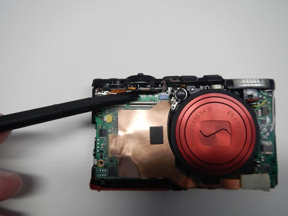
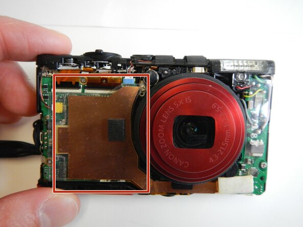
- Carefully remove the large copper ribbon on the front of the camera (attached with adhesive pads).
- Remove the ribbon wire attached at the bottom right corner of the front of the camera. You do NOT need to remove this from the motherboard.
- Remove the two screws from the silver panel that was behind the LCD screen.
- Lift the flash housing up and forward from the top of the camera to carefully remove.
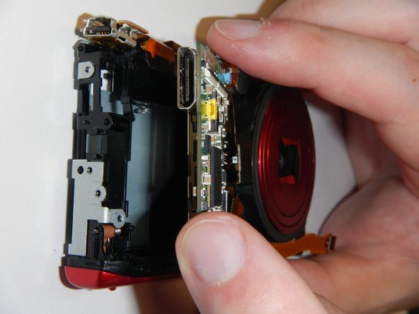
- Remove the top copper ribbon (for USB port) by gently prying it from the motherboard with the spudger.
- Remove the center copper ribbon (for CCD) using the same method as above.
- Remove the lower right copper ribbon as in step one.
- Remove the top screw on the motherboard. (2.5 mm).
- Remove the screw in the bottom left of the motherboard. (2.5 mm).
- Remove the screw located underneath the bottom copper ribbon. (3.0 mm).
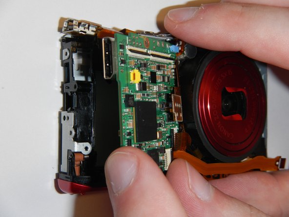
- Remove the motherboard from the frame by gently grasping the outside edge and pulling away.
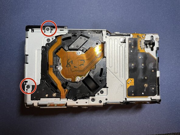
- On the back of the case, remove the top left corner screw. (3.0 mm).
- Remove the bottom right corner screw. (3.0 mm).
- Lift the silver frame away from the zoom lens to separate the two.