MacBook Pro 13" Retina Display Mid 2014 Upper Case Replacement
ID: 27851
Description: Use this guide to replace the upper case, which...
Steps:
- Remove the following ten screws securing the lower case to the upper case:
- Two 2.3 mm P5 Pentalobe screws
- Eight 3.0 mm P5 Pentalobe screws
- Throughout this repair, keep track of each screw and make sure it goes back exactly where it came from to avoid damaging your device.
- Wedge your fingers between the upper case and the lower case.
- Gently pull the lower case away from the upper case to remove it.
- The lower case is connected to the upper case with two plastic clips near its center.
- During reassembly, gently push down the center of the lower case to reattach the two plastic clips.
- If necessary, remove the plastic cover adhered to the battery contact board.
- Use the flat end of a spudger to lift the battery connector straight up out of its socket on the logic board.
- Be sure you lift up only on the connector itself, not the socket, or you risk permanent damage to the logic board.
- Bend the battery connector up out of the way to prevent accidental contact with its socket during your repair.
- Remove the two 2.1 mm T5 Torx screws securing the logic board end of the I/O board cable bracket.
- Grasp the I/O board cable bracket with a pair of tweezers and remove it from the MacBook.
- Use the flat end of a spudger to pop the I/O board connector straight up off its socket on the logic board.
- Be careful to only pry up on the I/O board cable, not on the socket itself or you risk damaging your logic board.
- Lift the logic board end of the I/O board cable straight up to bend it out of the way.
- To avoid damage to the cable, fold only at the bend in the I/O board end of the cable.
- Carefully tuck the tip of a spudger under the right speaker cable near the connector and lift it up out of its socket on the logic board.
- Carefully peel the right speaker cable off the upper case.
- Remove the following screws securing the right speaker to the upper case:
- One 5.7 mm T5 Torx screw
- One 6.5 mm T5 Torx screw
- One 3.8 mm T5 Torx screw
- Lift the right speaker from the cable end and pull it free from the case.
- Insert the tip of a spudger under the left speaker cable near the connector and lift it up out of its socket on the logic board.
- Be careful not to damage any surface-mounted components.
- Remove the following screws securing the left speaker to the upper case:
- One 5.7 mm T5 Torx screw
- One 6.5 mm T5 Torx screw
- One 3.8 mm T5 Torx screw
- Lift the corner of the left speaker up and slide it out around the battery to remove it from the upper case.
- Be careful not to snag the speaker cable on the screw hole post in the side of the case.
- We recommend that you clean your microwave before proceeding, as any nasty gunk on the bottom may end up stuck to the iOpener.
- Place the iOpener in the center of the microwave.
- For carousel microwaves: Make sure the plate spins freely. If your iOpener gets stuck, it may overheat and burn.
- Heat the iOpener for thirty seconds.
- Depending on the wattage of your microwave, more or less time may be required. The iOpener is sufficiently heated when it's barely too hot to touch.
- Throughout the repair procedure, as the iOpener cools, reheat it in the microwave for an additional thirty seconds at a time.
- Be careful not to overheat the iOpener during the repair. Overheating may cause the iOpener to burst. Do not attempt to heat over 100˚C (212˚F).
- Never touch the iOpener if it appears swollen.
- If the iOpener is still too hot in the middle to touch, continue using it while waiting for it to cool down some more before reheating. A properly heated iOpener should stay warm for up to 10 minutes.
- Remove the iOpener from the microwave, holding it by one of the two flat ends to avoid the hot center.
- The iOpener will be very hot, so be careful when handling it. Use an oven mitt if necessary.
- If you don't have a microwave, follow this step to heat your iOpener in boiling water.
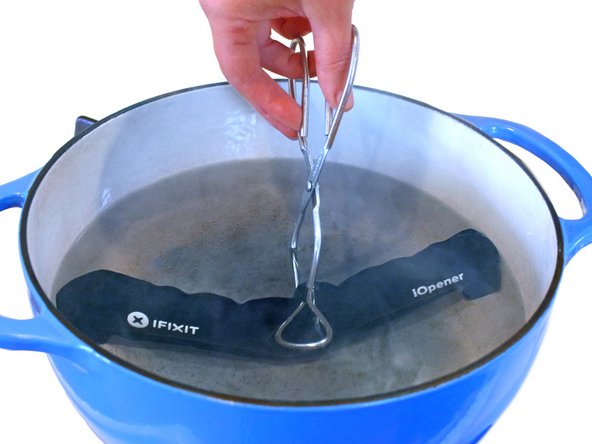
- Fill a pot or pan with enough water to fully submerge an iOpener.
- Heat the water to a boil. Turn off the heat.
- Place an iOpener into the hot water for 2-3 minutes. Make sure the iOpener is fully submerged in the water.
- Use tongs to extract the heated iOpener from the hot water.
- Thoroughly dry the iOpener with a towel.
- The iOpener will be very hot, so be careful to hold it only by the end tabs.
- Your iOpener is ready for use! If you need to reheat the iOpener, heat the water to a boil, turn off the heat, and place the iOpener in the water for 2-3 minutes.
- Remove the five 3.7 mm T5 Torx screws securing the battery to the upper case.
- Your specific unit may only have one screw securing the battery's circuit board to the frame.
- The liquid adhesive remover provided in your iFixit battery replacement kit can affect the antireflective coating on your MacBook Pro's display.
- To protect your display, place a sheet of aluminum foil between the display and keyboard and leave it there while you work.
- If you have an iFixit battery kit with liquid adhesive remover, it's time to get it prepped.
- Alternatively, if you are using the hot iOpener method, skip the following three steps.
- iFixit adhesive remover contains acetone, a mild skin and eye irritant.
- Wear eye protection when handling and applying the adhesive remover. (Eye protection is included in your kit.)
- Do not wear contact lenses without eye protection.
- Protective gloves are also included in your kit. If you are concerned about skin irritation, put your gloves on now.
- Pull off the black rubber stopper from your bottle of adhesive remover.
- Twist to loosen or remove the bottle cap before you cut the applicator tip.
- This unseals the bottle and allows the pressure to equalize before you cut the applicator tip. If you skip this step, the adhesive remover may spray out unexpectedly when the tip is cut.
- Use scissors to cut off the sealed tip of the applicator.
- Cutting close to the narrow tip will give you better control so you can apply the adhesive remover in small amounts.
- Twist and close the bottle cap securely before you proceed further.
- Apply a few drops of adhesive remover evenly under the edge of the rightmost battery cell.
- You don't need to use very much. The small bottle contains more than twice the amount of solvent needed to remove all the battery cells.
- Wait 2-3 minutes for the liquid adhesive remover to penetrate underneath the battery cell before you proceed to the next step.
- Use more adhesive remover if needed, but do not apply more than a few drops at a time. Using too much can allow the adhesive remover to make its way to the backside of your keyboard and potentially damage it.
- If you don't have a liquid adhesive remover, you'll be using a hot iOpener to warm and soften a section of the adhesive securing the battery to the upper case, and then carefully prying at that point.
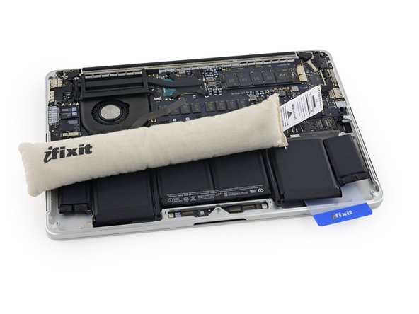
- Use the hot iOpener to cover half of the two right-most battery cells.
- After about a minute, reheat the iOpener and move it to cover the other half of the right-most battery cells.
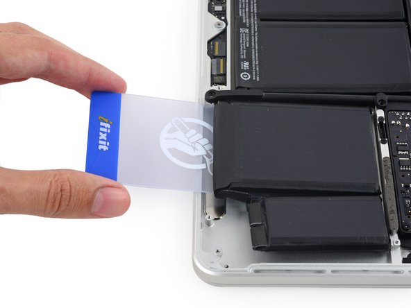
- Push a plastic card between the right-most battery cell and the upper case, cutting the adhesive between the two.
- Throughout this procedure, be careful not to damage any of the battery cells with your tools. A damaged lithium-ion battery may leak dangerous chemicals and/or catch fire. Use only plastic pry tools.
- When using the hot iOpener method, if you encounter significant resistance to prying, stop and use the iOpener to reheat the section you're working on.
- Use the plastic card to pry the right-most battery cell up from the rear case.
- Repeat this procedure with the adjacent battery cell:
- Apply a small amount of liquid adhesive remover under the battery cell, and wait 2-3 minutes for it to penetrate and soften the adhesive.
- Alternatively, re-heat this section with your iOpener if needed.
- Push a plastic card about an inch between the battery cell and the upper case, and slowly pry the cell up to separate all of the adhesive.
- Temporarily leave your plastic card underneath the two rightmost battery cells to prevent them from re-adhering to the upper case.
- If using an iOpener, reheat it and reapply it, this time to the left-most battery cells.
- Again, leave the iOpener in each position for about a minute, reheating in between, to heat each half of the left-most battery cells.
- Repeat the above procedure to separate the two leftmost battery cells from the upper case.
- Remember to apply a small amount of adhesive remover to each battery cell, and wait 2-3 minutes for it to penetrate and soften the adhesive.
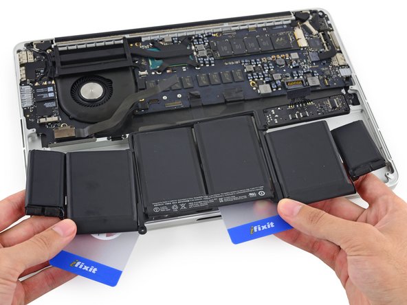
- Use a second plastic card to separate the two leftmost battery cells from the upper case.
- Leave the second card in the corner between the two left cells.
- In the following steps, you can either use a third card, or the card from the right corner. The right corner adhesive should be dry/cool enough that the cells can easily be pulled up again when needed.
- To separate the adhesive securing the final two, middle battery cells, apply a few more drops of liquid adhesive remover (or your iOpener) to each cell.
- Apply the adhesive remover sparingly, since the trackpad lies beneath this area of the battery.
- It may help to elevate one side of your MacBook Pro a few inches so that the adhesive remover flows in the correct direction, underneath the battery cells. You can use a sturdy book or foam block to prop up one side of your MacBook Pro while you work.
- Insert the card about an inch between the left-center battery cell and the upper case, separating the adhesive between the cell and the case.
- Pull the card back out and insert it about an inch between the right-center battery cell and the upper case, separating the adhesive between the cell and case.
- By this point, the outer cells should be free, and you should only encounter resistance from the two center cells. If this is not the case, go back and completely loosen the four outer-most cells from the upper case.
- Pry up on the two center cells to separate the last of the adhesive and lift the battery from the device.
- Remove the battery.
- Before installing your new battery, remove all the old adhesive from the MacBook Pro's case.
- With a little luck, you can slowly pull out each strip of adhesive with your fingers.
- Otherwise, soak each section of adhesive with a bit of adhesive remover for 2-3 minutes, and then scrape it out with an opening pick or one of the other tools in your kit. This can take quite a bit of work, so be patient.
- Mop up any remaining adhesive remover and give your MacBook Pro a few minutes to air dry.
- The replacement battery included in your iFixit kit comes with adhesive pre-installed. Test the battery's fit and alignment carefully before peeling off the film covering the adhesive, and then press each cell firmly into place. If any additional films/liners are present that weren't on your original battery, remove them now.
- Calibrate your newly installed battery: charge it to 100%, and keep charging it for at least 2 more hours. Unplug and use it normally to drain the battery. When you see the low battery warning, save your work, and keep your laptop on until it goes to sleep due to low battery. Wait at least 5 hours, then charge your laptop uninterrupted to 100%.
- If you notice any unusual behavior or problems after installing your new battery, you may need to reset your MacBook Pro's SMC.
- Place a reheated iOpener over the trackpad cover plate to soften the adhesive securing it to the upper case.
- Be careful not to overheat the iOpener during the repair. Always wait at least two minutes before reheating the iOpener.
- Use a plastic opening tool to carefully pry the trackpad cover plate up from the upper case.
- Go slowly and carefully to avoid putting any visible creases in the plate.
- Use a plastic opening tool to slowly and carefully peel the trackpad cover plate up off the upper case.
- Gently peel the plate up to remove it.
- If necessary, peel back any tape covering the trackpad cable connector.
- Use the tip of a spudger to flip the retaining tab on the ZIF connector.
- Pull the trackpad ribbon cable straight out of its socket on the logic board.
- Wedge the flat end of a spudger underneath the upper case opening where the trackpad ribbon cable passes is routed through.
- Gently pry the trackpad ribbon cable from the adhesive securing it to the upper case.
- Remove the following screws securing the trackpad brackets to the trackpad and upper case.
- Four 2.2 mm T5 Torx screws
- Four 1.7 mm T5 Torx screws
- Use tweezers to remove the two trackpad mounting brackets from the upper case.
- To avoid scratching the display, open the computer about 90º and set it on end.
- Carefully guide the trackpad ribbon cable through the slot cut in the upper case.
- This will push the trackpad up out of its recess in the top of the upper case.
- Guide the trackpad out of the upper casewith your other hand, so it doesn't fall.
- Gently pull the trackpad away from the upper case, being careful not to snag the ribbon cable.
- Grab the black plastic tab to flip the display cable connector open and pull it straight out of its socket on the logic board.
- Pull in the direction of the cable, parallel to the logic board. Do not pull up.
- Pull the DC-In board connector straight out of its socket on the logic board.
- Remove the two 3.5 mm T5 Torx screws securing the MagSafe DC-In board to the upper case.
- You may need to gently push the display cable out of the way to expose the screws.
- Use the MagSafe DC-In board cable to pull the board out and up from the upper case to remove it.
- Carefully remove the rubber fan bumper from the edge of the heat sink.
- The fan bumper wraps around the heat sink and fits into slots in the fan duct. During reassembly, be sure to fit the tabs into the notches in the fan duct.
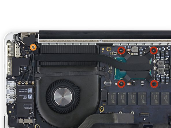
- Use the flat end of a spudger to peel the four foam stickers off of the heat sink screws.
- Remove the following screws securing the heat sink:
- Four 2.6 mm T5 screws
- One 2.4 mm Phillips #000 screw
- In the Early 2015 model, this is a silver 2.7 mm T5 screw.
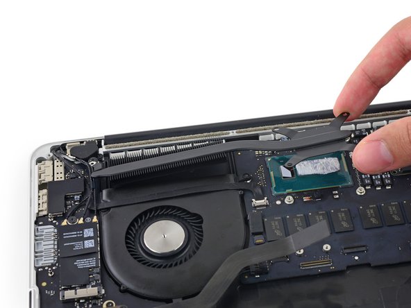
- Remove the heat sink from the laptop.
- Use the thermal paste application guide to reapply the thermal paste before reassembly.
- Use the tip of a spudger to push on either side of the the iSight camera cable connector and walk it out of its socket on the logic board.
- Peel the iSight camera cable up off the fan housing to fold it out of the way.
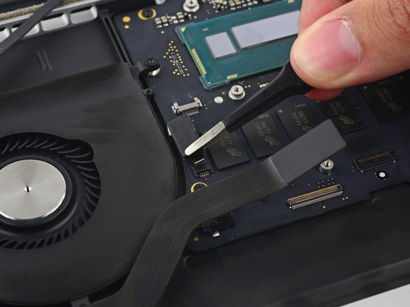
- Use the tip of a spudger to flip the tab on the fan's ZIF connector.
- Carefully pull the fan cable from its connector.
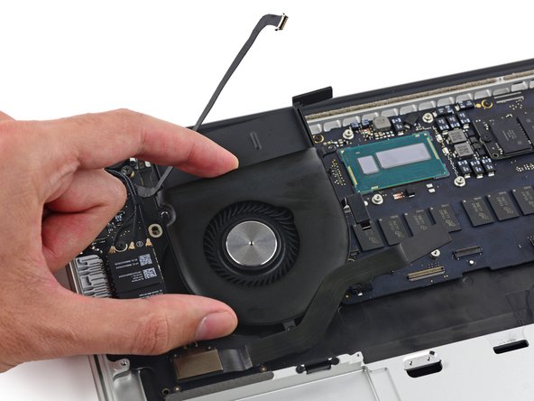
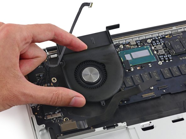
- Remove the following screws securing the fan to the upper case:
- One 5.0 mm T5 Torx screw
- Two 3.6 mm T5 Torx screws
- Lift the end of the fan from the heat sink cavity and pull it up and out toward the hinge of the laptop to remove it.
- Insert the tip of a spudger under each of the antenna cables near their connectors and pry up to disconnect them from the AirPort board.
- The three cables are coded with black sleeves of different lengths. During reassembly:
- Connect the long-sleeved cable to the center socket.
- The short-sleeved cable connects next to the screw.
- The remaining cable has no sleeve, and connects in the last empty socket, next to the fan.
- When reconnecting the antenna cables, run them over the camera cable, not underneath.
- With the tip of a spudger, push on either side of the I/O board connector to walk it out of its socket on the logic board.
- Remove the following screws securing the I/O board to the upper case:
- One 3.5 mm T8 Torx standoff screw
- One 3.5 mm T5 Torx screw
- Lift the I/O board cable end of the I/O board and pull toward the logic board to free the ports from the upper case.
- Remove the I/O board.
- When reinstalling the I/O board, be sure to slide the USB ports' metal EMI fingers under the side of the case, not over.
- Use the flat end of a spudger to disconnect the keyboard backlight cable and move it out of the way.
- If necessary, peel back any tape covering the microphone cable ZIF connector.
- Use the tip of a spudger to flip the retaining tab on the microphone cable ZIF connector.
- Pull the microphone cable straight out of its socket on the logic board.
- If necessary, peel back any tape covering the keyboard cable connector.
- Use the tip of a spudger to flip the retaining tab on the ZIF connector.
- Pull the keyboard cable straight out of its ZIF socket on the logic board.
- Remove the five 3.5 mm T5 Torx screws securing the logic board to the upper case.
- When reassembling, install all five screws loosely, position the logic board, and then tighten evenly.
- Lift the processor end of the logic board up slightly and pull it toward the fan recess to free the ports from the edge of the upper case and remove the logic board.
- When reinstalling, make sure the keyboard, keyboard backlight, and microphone cables don't get trapped beneath the logic board.
- Also be sure to slide the ports' metal EMI fingers under the side of the case, not over.
- Use a pair of tweezers to lift the rubber hinge covers up off the right and left display hinges.
- Remove the 3.2 mm T5 Torx screws (one on each side) securing the aluminum hinge brackets to the upper case.
- Use a pair of tweezers to lift aluminum hinge brackets off the right and left display hinges.
- Remove the four inner 5.3 mm T8 Torx screws (two on each side) securing the display to the upper case.
- Open the MacBook Pro a little wider than 90 degrees, and place it on end, as shown.
- While holding the display and upper case together with your left hand, remove the remaining T8 Torx screw from the lower display bracket.
- Be sure to hold the display and upper case together with your left hand. Failure to do so may cause the freed display/upper case to fall, potentially damaging each component.
- Remove the last remaining T8 Torx screw securing the display to the upper case.
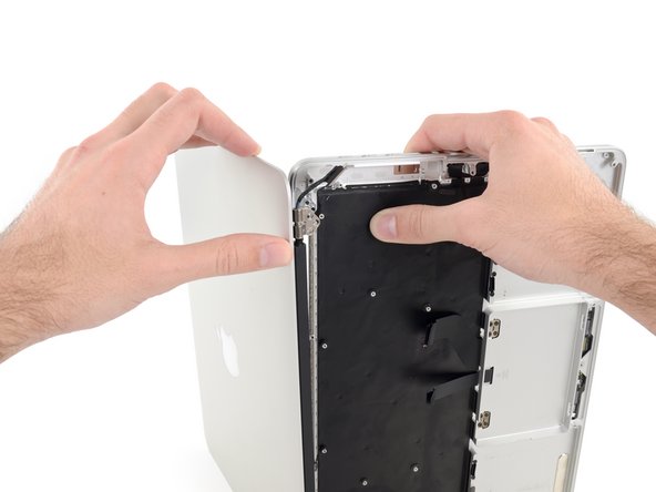
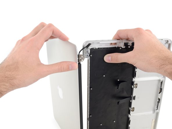
- Grip both halves of the device, one in each hand.
- Gently push forward on the bottom half of the device to detach it from the display assembly.
- Carefully set each component aside, making sure to set down the lower half keyboard-side down.
- Place the MacBook on a heated iOpener for about a minute to soften the adhesive securing the dual microphone cable.
- Insert the tip of a spudger under the rubber microphone cable cover to free it form the upper case.
- Remove the rubber microphone cable cover.
- Insert the tip of a spudger under the connector end of the microphone ribbon cable and lift to peel that section up from the upper case.
- Insert the tip of a spudger under the right-hand portion of the microphone ribbon cable and slide it toward the screw post to free it from the upper case.
- Remove the microphone cable from the upper case.