Acer Iconia Tab A3-A10 Touchscreen Replacement
ID: 35623
Description: You can find digitizer for about 60 usd / 50...
Steps:
- Start to unclip the back cover inserting a plastic opening tool from microSD connector.
- Continue to release the back cover uncliping counter-clockwise.
- Continue turning around.
- And that's it !!
- Remove the yellow tape.
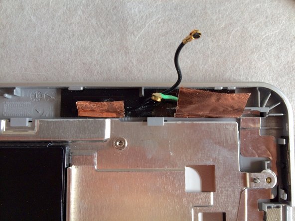
- Unplug both wifi antena connectors. (Green and Black wires)
- Remove the single Phillips 000 screw securing the volume buttons circuit board.
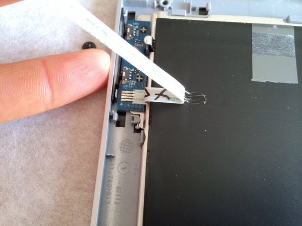
- Pull the flex cable out the connector.
- Grab it by the blue plastic strip..
- Gently pull up the flex cable to unstick it from the metal plate and from the battery pack.
- Then remove the volume buttons circuit board.
- For the A3-A11 (3G) model, the cellular board is placed just over the flex cable, where sticked to the metal plate. (you can see the empty spot for the connector on the logic board)
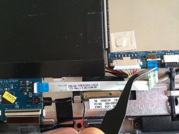
- Pry up the white bars to unlock the two connectors.
- Remove the flex cable pulling it out its two connectors.
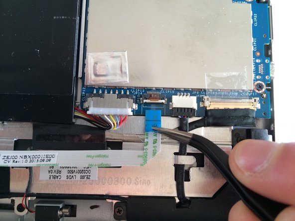
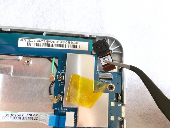
- Pry up the black bar to unlock the camera connector
- Gently pull away the camera out the connector.
- Unplug both connectors just pulling them out.
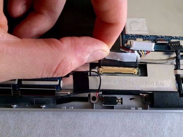
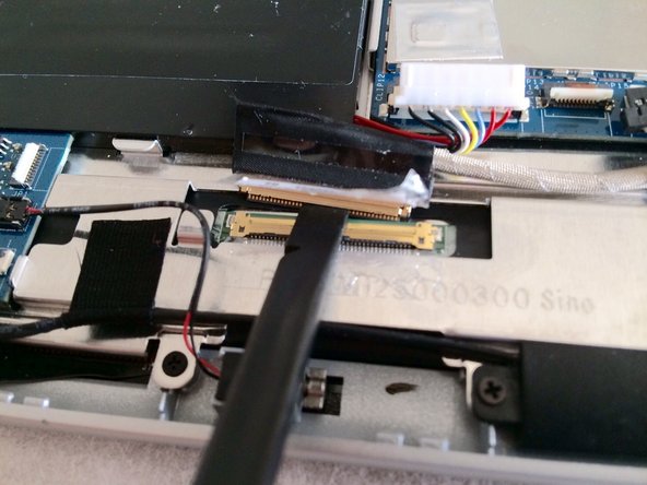
- Unlock both touchscreen connectors pulling up grey bars.
- Pull out the two flex cables.
- Peel off the cristal tape pieces upon each connector side.
- You can :
- Pull out grabbing the cable connector by black taped part.
- Push the cable connector with a spudger, at both of its extremity. Or with a large flat one on the gold part.
- Both ways silultaneously...
- Be careful !!
- Remove the display cable.
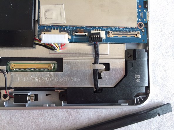
- Pry up the vibrator to release it.
- Remove the four Phillips screws securing the two speakers.
- Peel off the two tape pieces securing the cable linking speakers.
- Remove speakers and cable.
- Remove the four Phillips screws securing the motherboard.
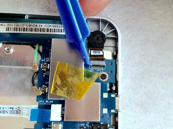
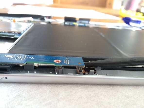
- Disconnect the front facing camera with a spudger.
- Introduce a flat spudger between the motherboard and the camera flex cable.
- Then, rotate the spudger 90°.
- It should separate easily !
- Do not use excessive force. If it does not work, you probably are not correctly placed.
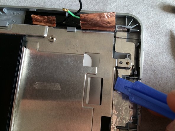
- Peel off coper tapes from the metal plate.
- Do not use excessive force to peel coper tapes off the metal plate. Doing so may tear the coper.
- Peel off the aluminium tape making ground contact.
- Do not use excessive force to peel the aluminium tape off the metal plate. Doing so may tear the aluminium.
- Remove two remaining Phillips screws securing the metal plate.
- Release the touchscreen circuit board from the adhesive securing it to the display below.
- Introduce a spudger and unstick the back of the circuit.
- There are no components protruding from the underside of the board !
- 3 points to remove the metal plate with the battery pack :
- Yellow arrows : only two small clip still retain the metal plate (all screws were removed during previous steps).
- Blue arrows : lift up the metal plate until pins are released (blue circles).
- Orange arrows : pull towards you the metal plate to release the plate from top cleats.
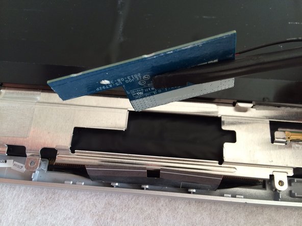
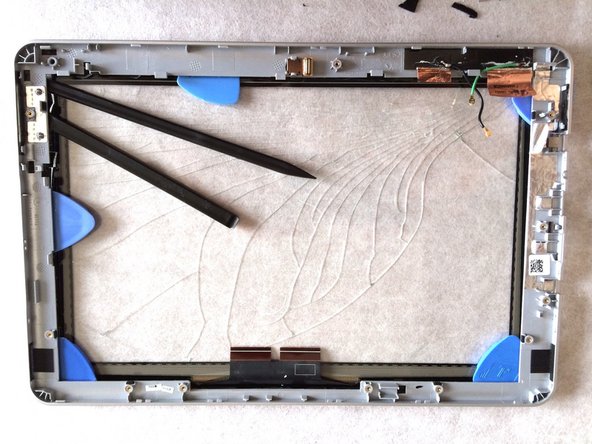
- Lift off the display to remove it.
- There are eight rubber pads which hold gently the display to the plastic frame.
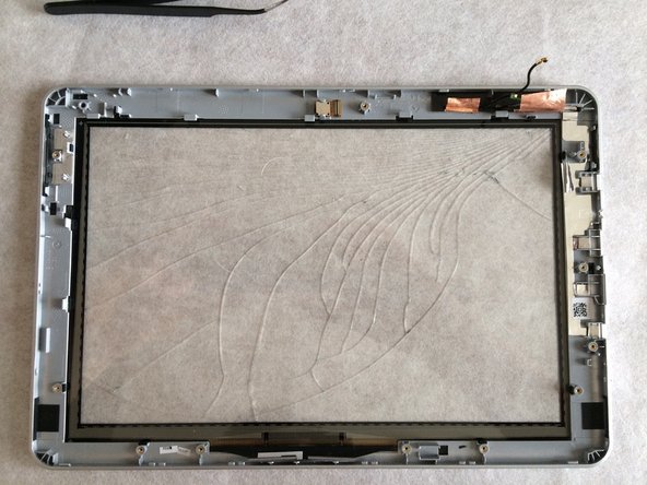
- Here starts the painfull work.
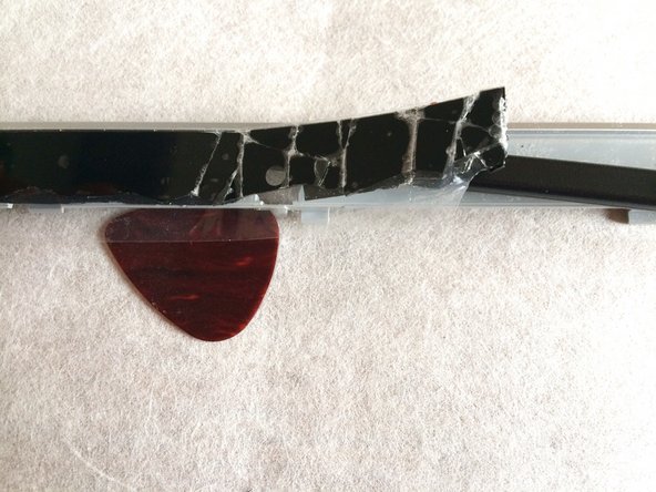
- The touchscreen is strongly sticked to the frame with a foamed double-sided tape.
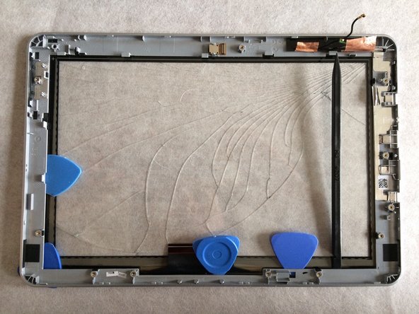
- You can heat up the taped area with an hairdryer to decrease to tape resistance.
- When soften, introduce plastic opening tools to separate frame and touchscreen.
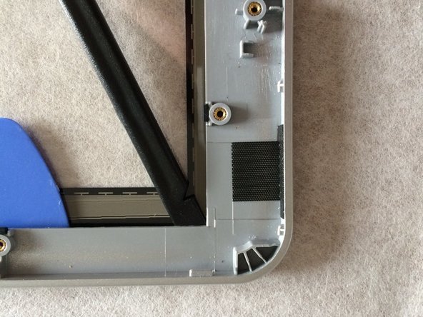
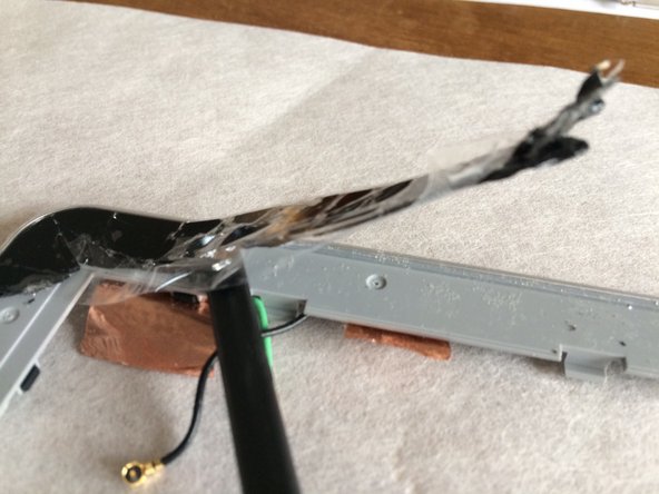
- Be careful as the touchscreen will broke easily in little pieces when prying up.
- Introduce plastic opening tools, turning around to separate frame and touchscreen.
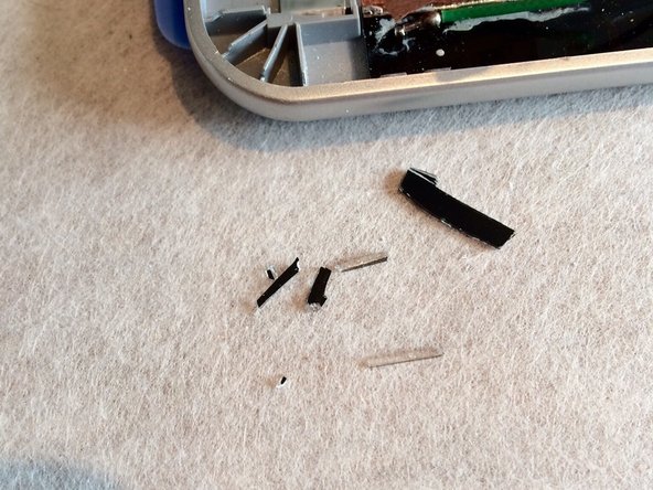
- Be careful as the touchscreen will broke easily in little pieces.
- As the touchscreen will probably be broken in a lot of pieces, put cristal tape on remaining touchscreen fragments.
- It will prevent breaking in multiple tiny bursts. And protect your eyes !
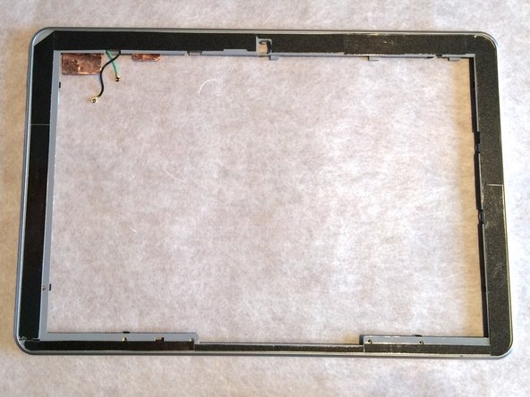
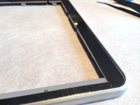
- Remove all remaining tape marks before applying new tape.
- I used standard foamed double-sided tape.
- Cut to the right size so there are no remainming free space, which would allow dirt to squeeze through !
- Peel off the interior protective plastic film from the new touchscreen.
- Place it into the main frame.
- Press firmly to the adhesive to tighten it!