Sonos Connect Bottom Motherboard Replacement
ID: 61572
Description: There are two boards for the device, a green...
Steps:
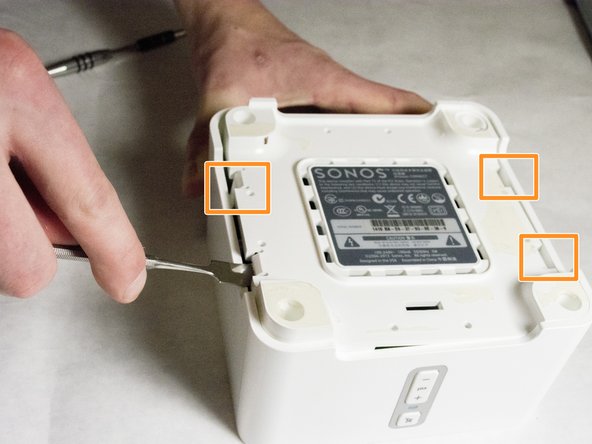
- Start by using a spudger or plastic opening tool to remove the bottom cover.
- When working with electronics, it's important to choose a tool that's ESD-safe to avoid accidental damage to the device. The regular black nylon spudger or a plastic opening tool should be used whenever possible.
- Once enough of the glue is removed, peel the cover off by hand,
- Remove the four 7.5mm length Philips head screws under the rubber cover.
- Use a nylon spudger to unsnap the bottom from the sides.
- Pry until the remaining three points are unsnapped.
- Once unsnapped, lift the cover.
- Remove the connection for the front buttons to fully remove the cover.
- Use a plastic opening tool or spudger to remove the adhesive covering the the WIFI connectors.
- Gently pull the wires at the connection point to disconnect them from the motherboard.
- Remove the two pieces of glue holding the WIFI card in place.
- Scrape the glued pad underneath the WIFI card to seperate the card from the board.
- Push apart the two clips holding the WIFI card in the connection.
- Pull the WIFI card out of the connection.
- When putting the new WIFI card in, put the card in the connector first, then push downward until it clicks.
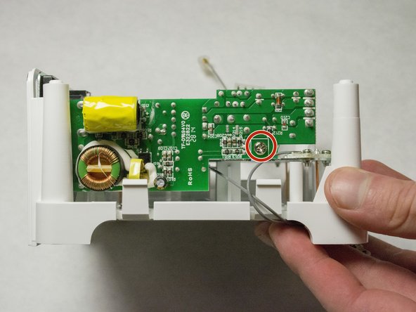
- Remove the 7mm length Phillips screw holding the board in place.
- Flip the board over to access the Molex Cable.
- Disconnect the Molex Cable from the top motherboard.
- Remove foam protective insulator from the bottom board.
- Picture shows the side of the device.
- Remove the 7mm length Phillips screw from the power supply motherboard.
- Remove the adhesive backed rear label by using a spudger.
- Remove the two 8mm length screws as shown.
- Pull the power supply out of the back of the device.
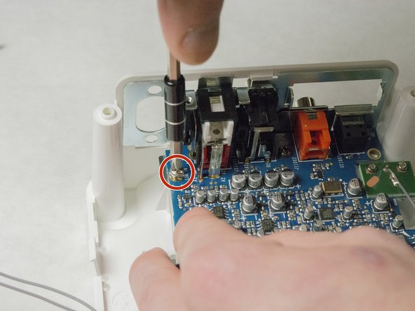
- Remove the two 7.5mm length screws on the top of the board.
- Remove the other two 8mm length screws on the back of the device. You might have already removed the screws for the power supply, and that's OK!
- Slide the board out from the plastic casing.
- You must pull the board out from back to front, because of the plugs on the back of the board.