Alcatel One Touch Pop 7 Display Assembly Replacement
ID: 74615
Description: If your device is not displaying picture or has...
Steps:
- Begin working by using the plastic opening tool to remove the back cover of your Alcatel One Touch Pop 7. Opening the flap as shown in the picture will give you an easier start.
- With the back cover removed you will now want to disconnect the battery. Use the tweezers and gently pull the wires as shown in the second picture.
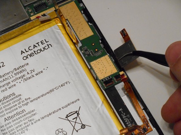
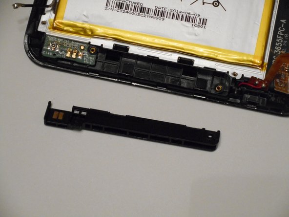
- The volume button assembly is in the top left corner of the tablet. To begin, you will have to pull the small black tab of the ZIF connector, shown in the second picture, to be able to remove the assembly. The tab is on a hinge so it should not be pulled off completely.
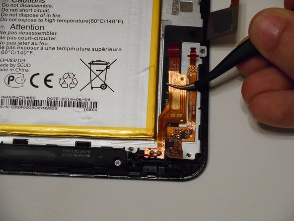
- Pull the copper ribbon cable from the tab. It should be easily removed, as the ZIF connector is the only thing holding it in place.
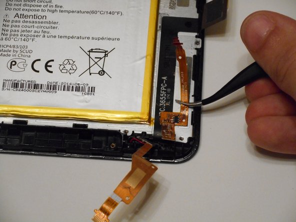
- Next up is removing the volume button assembly. Another easy removal, simply pull the assembly away from the device and you're done with the removal process.
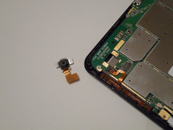
- The camera is in the top left corner of the tablet. To begin removal, use the tweezers to gently disconnect the ribbon cable attached to the camera.
- Pull the actual camera piece from the camera slot. It may stick a bit but it shouldn't be too difficult.
- We now need to remove 3 ZIF connectors, all located in the bottom right quadrant. The order they are disconnected doesn't matter.
- Disconnect the ribbon cable and move it out of the way of the motherboard.
- Using a PH00 screwdriver to remove these seven 2mm screws and place them in a safe spot where you won't lose them.
- With the screws removed, you can now remove the motherboard. Using tweezers or just your fingers, pick up the motherboard and place it to the side.
- Using a PH00 screwdriver, remove the 6 highlighted 2mm screws.
- Pull the ribbon cables away from the back of the display screen. The right cable can be removed completely while the left will stay attached to the front casing.
- Use the plastic opening tools to pry off the plastic piece at the bottom of the device.
- Pull away the digitizer ribbon cable using the tweezers. It will stay attached to the front casing.
- With the screws and ribbon cables removed, the display panel can be separated from the digitizer. You can pull the display panel away from the digitizer or turn it vertically and catch the display panel as it falls out.