Canon PowerShot A75 LCD Screen Replacement
ID: 9079
Description: Use this guide to replace the Canon PowerShot...
Steps:
- Turn the camera over and locate the "BATT OPEN" sliding switch.
- Slide the switch to the right.
- The battery cover should slide down and spring open.
- Remove the 4 AA batteries.
- Watch for the orientation of the batteries as they slide out.
- The battery orientation is shown under the battery flap itself and on a sticker next to the battery flap.
- Remove the three 2.5mm screws on the bottom of the camera.
- Remove the 3.8mm screw underneath the flap that covers the A/V port.
- Remove the 2.4mm screw located underneath the cover of the memory card slot.
- Open the memory card slot by sliding it laterally until you hear a click.
- Remove the 5.9mm screw in the upper corner of the memory card slot.
- Remove the two 4.1mm screws at the bottom of the battery flap.
- Lift the shutter button and speaker part from the top of the camera.
- DO NOT pull the part too hard because there is a plug connecting the speaker to the camera.
- Using a pair of tweezers, grab the plug that connects the speaker to the camera and gently pull it out.
- Remove the rightmost 4.2mm screw underneath the battery cover, not the center screw.
- Separate the back casing and front casing of the camera using your hands.
- Pulling the two halves apart can be difficult, especially at the top. Use a moderate amount of force.
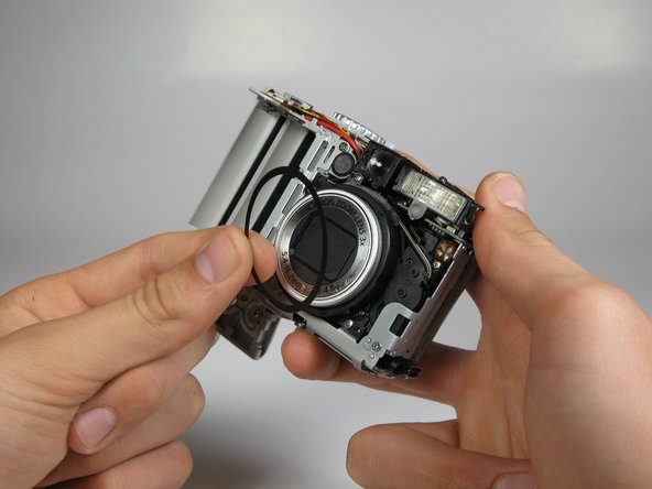
- On the front of the camera, press the button on the lower left of the lens.
- Twist the outer lens casing counter-clockwise and slide it out.
- Take off the front casing.
- There is a black rubber washer around the lens that comes out after you take the casing off. Make sure to replace it when putting the camera back together.
- Remove the 4.4mm screw directly behind the eyepiece on the top of the camera.
- Remove the 4.3mm screw to the right of the eyepiece housing in the crack in between the eyepiece and a ribbon cable on top of the camera.
- Gently wiggle the eyepiece out of its place. It should snap out of place.
- There should be a white ribbon cable underneath attached to the motherboard.
- Locate the white cable on top of the camera where the eyepiece was.
- Using tweezers, grasp the white cable as close to the connection point as possible and gently remove the cable.
- The cable should just slide out with a slight tug.
- Remove the 2.9mm screw directly underneath the white cable.
- Remove the 4.2mm screw directly under the battery flap.
- Remove the 3.4mm screw inside a deep hole on the back copper panel beneath the circular mode switcher.
- This screw is a little difficult to get out.
- Remove 2.5mm the screw in the silver housing on the bottom of the camera. This screw is holding the back panel in.
- Remove the 3.4mm screw near the bottom of the back face of the camera on the copper ribbon.
- Remove the 2.9mm screw on the back face of the camera in the bottom left corner.
- Locate the copper ribbon cable attaching the LCD screen to the bottom motherboard.
- Grasp the cable near the white connector and gently remove the cable.
- Gently pull back the LCD screen to around 45 degrees from the back of the camera.
- Do not pull the back panel too far, it is connected to the top of the camera with ribbon cables and is not meant to separate from the camera.
- Locate the larger ribbon cable connecting the screen to the body of the camera.
- Gently grasp and pull the cable from the motherboard. The cable should easily slide out.
- This ribbon cable may be easier to remove using your hands instead of the tweezers.
- The LCD should now be out after the cable is removed.