Liberate BT Speakers Micro USB socket Replacement
ID: 99048
Description:
Steps:
- First step is to pry the faceplate off the backing. I wasn't sure which step came first but after getting it apart I realized this is 100% the first step.
- Use a flathead screwdriver and gently lever it under the metal plate. This needs doing all the way around lightly before prying it up. Try not to give it enough force as to bend the metal, its not nessisary.
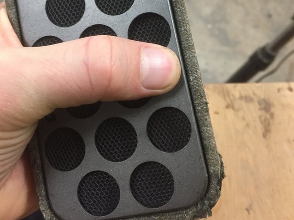
- The Next piece is the perforated screen. This piece is nestled neatly into the screw socket underneath it. Like the faceplate it just needs light prying to get off. Even lighter than the first step.
- Next you can clearly see the screws on the black sound drum piece. You need a small phillips screwdriver or a flathead. Be careful to pull this plate off gently as it has wires attached to it on the other side.
- Gently pull off the speaker plate leaving enough space to reach you hand inside.
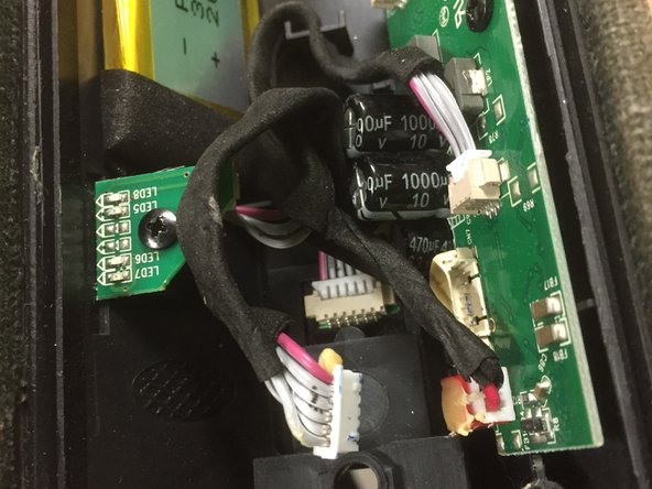
- Using your thumb and finger nail or the screwdriver, pull off the wire sockets from the housing on the motherboard. only grab the end flange that's attached to the wires.
- Do this to all the wires inside the speaker until the lowest one remains.
- Begin now to unscrew the 3 screws at the very bottom. They are holding onto the marley brand wooden plate. This plate must come off to reveal other mounting screws.
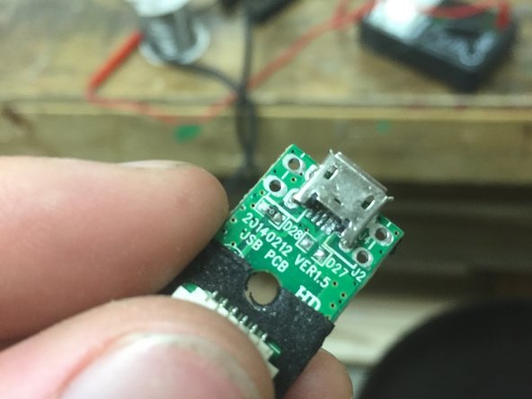
- With the wooden backplate gone, you can now unscrew the small circuit board holding the micro usb socket.
- You can also remove the rubber cover flap by pulling it off.
- For my particular problem, I needed a new insert inside the micro usb socket. I bought a new one at the local electronics store and used it's insert. The insert is where the pins inside the micro usb go to connect. They are then channeled down to the circuit and soldered to the board.
- Carefully solder the 5 pins to the board using a very fine tipped solder iron. Be sure to tin it with steel wool.
- Do not add more solder if there is still some on the circuit board!
- There is very little required to make a good connection from the circuit tracer to these very tiny pins.
- After soldering, check if it charges with a mirco USB cable. A small red light should turn on right under the usb socket.
- Reverse all the steps for tear down to put it all back together.
- Lightly press the final metal cover over into its place to secure.
- Done!